Chapter 7 Controller Section Theory of Operation
Introduction
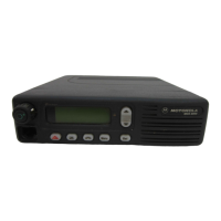
The radio is a microcontroller-based dual mode (trunked/conventional) transceiver. The
microcontroller determines the active state of the radio (transmit/receive), monitors radio status, and
processes operator commands entered from the keypad or the other radio controls.
In the Low and Mid Power versions of the radio all radio circuitry is contained on a single rigid printed
circuit board (PCB). In the High Power version of the radio, the physical arrangement of the circuitry
is the same except the power amplifier (PA) part of the transmitter is contained on a separate PCB.
The radio is composed of the following three major functions:
• RF (Receiver and Transmitter)
• Controller (Main Controller and DC Power Control and Regulation
• Control Head
The RF section is band specific circuitry described in one of the frequency range specific Volume 2s
depending on the band split (See “Related Publications” on page 1-1).
The Control Head connects to the radio via an 18 pin connector. There are three different control
head types of varying complexity: Model I, Model II and Model III. Control Head information is
covered in chapter 8 of the manual.
Theory Overview
The Controller section is physically separated into two functional sections, i.e. the Main Controller
and the DC Power Control and Regulation.
The controller section of the radio is primarily a microprocessor that controls the radio in accordance
with the firmware (model specific), the codeplug (customer specific), and commands input manually
by the radio operator. The radio operator inputs manual commands to the controller section using the
push-button and other controls located on the radio control head and some accessories. In addition
to its controlling functions, the controller section provides audio amplification of the audio signal from
the receiver section, supplies regulated and switched power to the radio, and interfaces with devices
outside the radio box.
The radio controller consists of 5 main functional sections. These are:
• voltage regulation
• power control
• interfacing
• microprocessor operation
• audio and signalling processing
The controller is based on the Motorola 68HC11F1 microprocessor (U0103). In addition to the
microprocessor, the controller has 3 external memory devices, signal MUX IC (U0105), and a
Support Logic IC (SLIC IV, SLIC IVa, or SLIC V, U0104). The 3 memory devices consist of a 32 kbyte
EEPROM (U0108), 8 kbyte SRAM (U0101), and a 256 kbyte or 1 Mbyte FLASH (U0102).

 Loading...