December 6, 2004 68P81083C20-D
5-6 Disassembly & Reassembly and Replacement Procedures: Disassembly to Transceiver Board Level
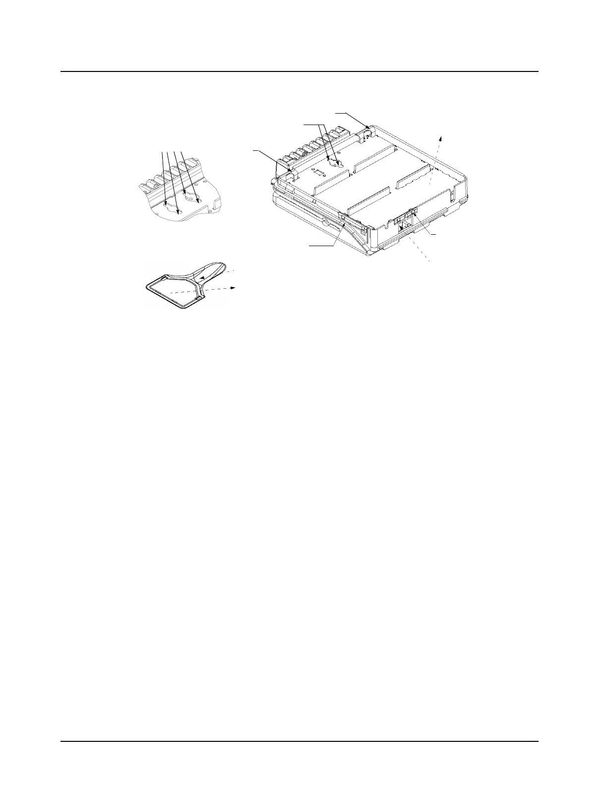
Figure 5-7. Removing the Transceiver Board - Mid Power Models (except 800 MHz and 900 MHz)
Remove the Transceiver Board
800 MHz and 900 MHz Models Only
1. Remove the Accessory Connector by sliding a finger into the recess on the chassis and push-
ing up on the connector tab to loosen the connection. Lift the connector out of the recess.
2. Remove all screws using a T-10 TORX driver.
3. Remove the power and antenna connector retaining clips by inserting a small flat blade
screwdriver between the clip and the top of the cavity wall and gently prying the clip upwards.
On Mid Power models: Remove the PCB clip and the Audio PA clip by inserting a flat-blade
screwdriver or like instrument between the clip and the side wall. Prying the clip upward to
disengage with the tabs on the wall.
4. Press on the 25 pin connector through the bottom of the chassis until the board is released
from the chassis.
5. Carefully remove the transceiver board by rotating it out of the chassis. Slowly lift the board
on the front edge while pushing up on the board through the accessory connector opening
(see Figure 5-8).
PCB Mount
Power Connector
Clip
Antenna Connector
Recessed Power
Amplifier Screws (UHF)
Audio PA
Recessed Power
Amplifier Screws (VHF)
1) Push up on board
2) Pull board
Clip
through accessory
connector opening
Clip
forward out
of chassis
Clip
Accessory Connector Detail
2) Pull connector
straight out
1) Slide finger
under tab
 Loading...