December 6, 2004 68P81083C20-D
5-18 Disassembly & Reassembly and Replacement Procedures: Transceiver Reassembly High Power Models
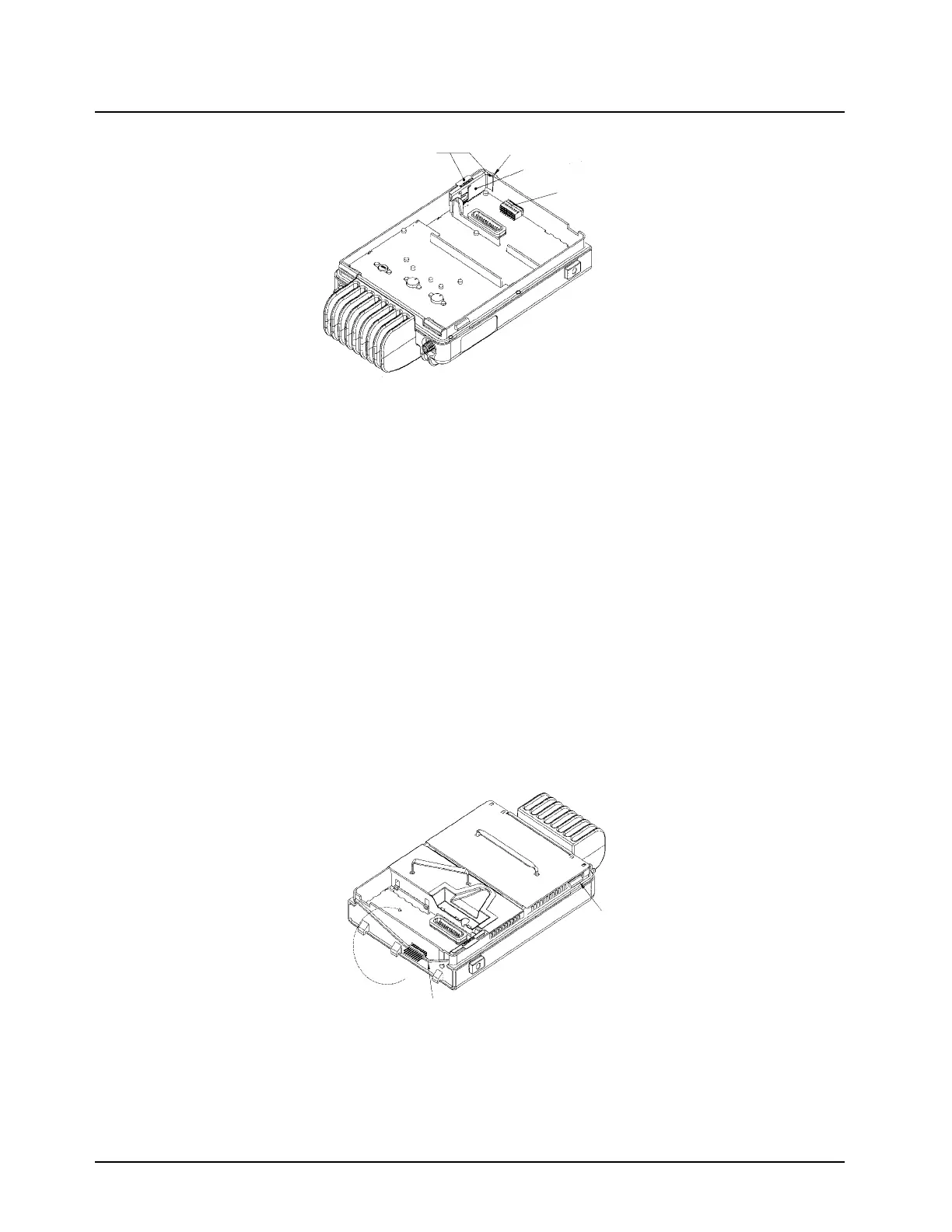
Figure 5-22. Inserting Audio PA Clip
1. Install the RF shield by placing it over the chassis with the front and back tabs inside the
chassis and side tabs outside the chassis walls. Push straight down applying even pressure
to the edges of the shield until they rest flush on the chassis wall. Repeat the same operation
for the PA shield.
2. Insert the 18 position connector (black side) through the opening in the chassis into the
female connector on the RF board.
NOTE: The 18 position connector is not symmetrical, therefore the black side must mate to the
connector on the transceiver board.
3. Place a new cover gasket around the chassis being sure it is placed under the locking tabs
and the v-shaped rail shown in Figure 5-23. To ensure that the gasket remains seated under
the rail, twist the gasket up and toward chassis between the fingers at the location of the low-
est point of “V”. Position the gasket under the rail and release.
4. Insert the 18 position connector (black side) into the female connector through the hole in the
front of the chassis.
5. Carefully guide the bottom cover front hole opening over the 18 position connector. Engage
the bottom cover over the hooks at the front of the chassis, rotate the cover back over the
chassis, and press down until the sides snap into place.
Figure 5-23. Installing Cover Gasket
6. Install the accessory connector assembly through the bottom side of the radio. Be sure to
install the connector straight down into the unit because otherwise it will catch on the housing
and no connection will be made.
NOTE: The radio will not function without the accessory connector.
Pressure!Points
Guide!Rail
Audio!PA!Clip
18!Position!Connector,
Female
Locking!Tab
(other!tab!on!opposite
side!of!chassis)
Gasket!twist
direction
Lowest!point!of!gasket
locating!feature!"V"
 Loading...