December 6, 2004 68P81083C20-D
5-12 Disassembly & Reassembly and Replacement Procedures: Reassembly of the Control Head
Reassembly of the Control Head
Model I
1. Place the LCD, color sheet, LCD frame, and elastomeric connector into the housing. Make
sure that the LCD aligns with the gasket in the housing.
2. Place the keypad into the board assembly, making sure that the keypad is flush with the
board.
3. Make sure that both the volume knob and potentiometer are both fully in the counter clock-
wise position before assembling the board into the housing.
4. Also make sure that the speaker is aligned with the speaker gasket and connected to the
board assembly.
5. During the installation of the internal speaker be sure that all eight snaps are engaged on the
Frame Lock. Be sure not to crimp the speaker wire.
Models II and III
1. Place the keypad into the control head housing.
2. Snap the light pipe into the housing. Alternate engaging snaps on each side for best result.
3. Make sure that both the volume knob and potentiometer are both fully in the counter clock-
wise position before assembling the board into the housing.
4. Snap the board assembly into the housing.
5. For model “II” only, attach the large rotary knob.
Transceiver Reassembly Low and Mid Power Models
Transceiver Reassembly
NOTE: Replace all gaskets at each servicing to ensure proper sealing of unit.
Be careful to use only very little thermal grease as an excessive quantity will deteriorate the
conductivity.
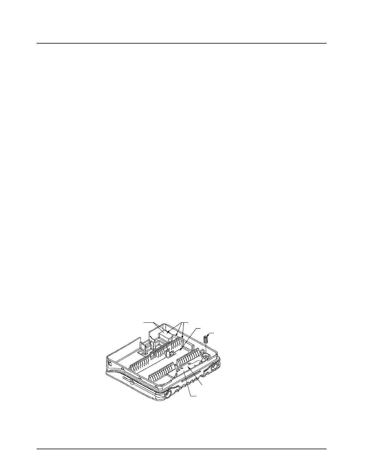
1. Inspect and reapply a THIN layer of thermal grease as needed to the areas shown in Figure
5-16.
Figure 5-16. Reassembly
2. Insert the diode spring.
Audio PA and Regulator Pedestals
Diode Spring
Chassis PA Pedestal
Apply Thermal Grease
to this raised surface
Apply Thermal Grease
to these raised surfaces
Board Slot Shield
 Loading...