68P81083C20-D December 6, 2004
Disassembly & Reassembly and Replacement Procedures: Disassembly to Transceiver Board Level
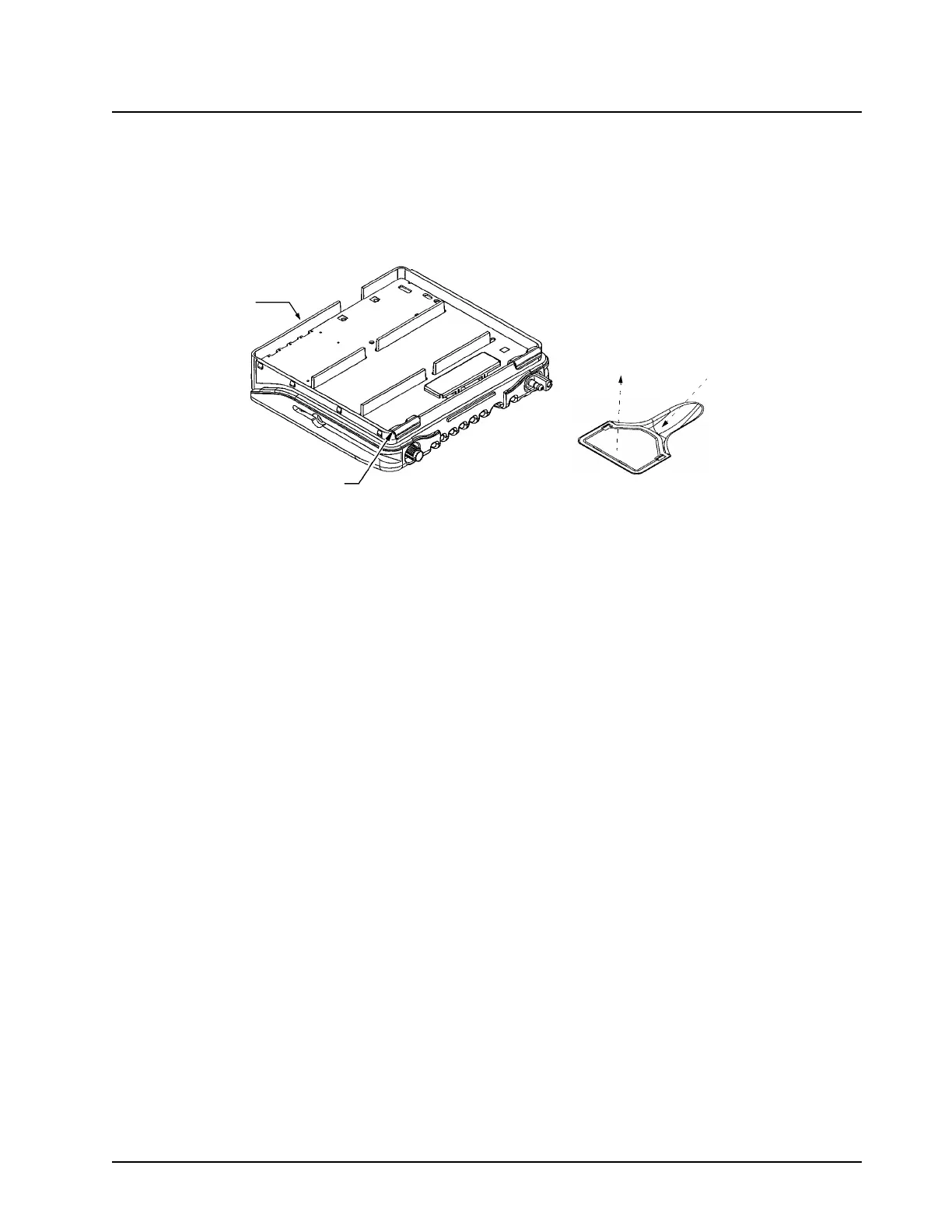
2. Remove all screws using a T8 or T-10 Torx Driver where appropriate. Remove the power and
antenna connector retaining clips by inserting a small flat blade screwdriver between the clip
and the top of the chassis wall and gently prying upwards (see Figure 5-6).
NOTE: Thermal grease can act as an adhesive and cause the leads of the power amplifier devices
to be over stressed if the board is lifted too quickly.
Figure 5-6. Removing the Transceiver Board - Low Power Models (except 800 MHz and 900 MHz)
3. Carefully remove the transceiver board by rotating it out of the chassis. Slowly lift the board
on the front edge while pushing up on the board through the accessory connector opening.
Pull the board forward out of the chassis.
Mid Power Models
1. Remove the Accessory Connector by sliding a finger into the recess on the chassis and push-
ing up on the connector tab to loosen the connection. Lift the connector out of the recess.
2. Remove the power and antenna connector retaining clips by inserting a small flat-blade
screwdriver or like instrument between the clip and the top of the cavity wall per area shown
in Figure 5-6. Gently prying upwards.
On 40W Power models only: While removing clips, do not rest screw driver on PA Ground-
ing Fence (P/N 2685629B01). Doing so will likely degrade the radio’s shielding performance.
3. Remove the PCB Clip and the Audio PA clip by inserting a flat-blade screwdriver or like
instrument between the clip and the side wall. Prying the clip upward to disengage with the
tabs on the wall.
4. Remove the recessed Power Amplifier Device screws using a T-8 Torx Driver, four on VHF,
two on UHF (see Figure 5-7).
5. Remove the remaining screws with a T-10 Torx Driver.
6. Carefully remove the transceiver board by rotating it out of the chassis. Slowly lift the board
on the front edge while pushing up on the board through the accessory connector opening.
Pull the board forward out of the chassis.
NOTE: Thermal Grease can act as an adhesive and cause the leads of the power amplifier devices
to be over stressed if the board is lifted too quickly.
Front
Pry Clip Off Here
Accessory Connector Detail
2) Pull connector
straight out
1) Slide finger
under tab
 Loading...