December 6, 2004 68P81083C20-D
5-8 Disassembly & Reassembly and Replacement Procedures: Disassembly to Transceiver Board Level
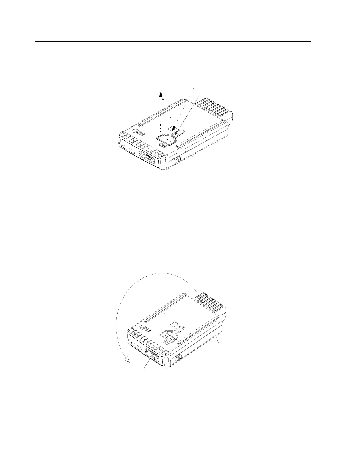
3. Remove the Accessory Connector by sliding a finger into the recess on the bottom cover and
pushing up on the connector tab to loosen the connection. Lift the connector out of the
recess. See Figure 5-10.
Figure 5-10. Removing the Accessory Connector
4. Insert a wide flat-blade screwdriver or like instrument in the recess area on the side of the
radio near the antenna and power connector ends (see Figure 5-11).
5. Pry the bottom cover off the chassis by pushing the handle of a screwdriver up and toward
the radio. This will disengage the snap between the bottom cover and the chassis.
6. Repeat Step 4 and Step 5 for the other side of the radio.
7. Rotate the bottom cover out and away from the chassis until it is completely free of the chas-
sis taking care not to damage the 18 position connector in the process.
Figure 5-11. Removing the Bottom Cover
8. Remove the cover gasket from the chassis.
Note the correctly assembled position of the main seal before removing.
Bottom!Cover
2)!Pull!connector
straight!out
1)!Slide!finger
under!tab
Accessory!Connector
Accessory Connector
Bottom Cover
1) Slide finger
under tab
2) Pull connector
straight out
Rotate Cover
Out and Away
in this Direction
10 Position Connector
Disengage Snap here
and on other side
Disengage Snap here
and on other side
18 Position Connector
Rotate Cover
in this Direction
Out and Away
 Loading...