December 6, 2004 68P81083C20-D
7-4 Controller Section Theory of Operation: Voltage Regulation
While SW B+ SENSE is on for 220 ms, the microprocessor starts execution, reads that the SW B+
SENSE is active, and sets the B+ CNTL output to a logic high to keep Q0510 switched on through
CR0510 beyond the 220 ms period. After this U0510-5 will return to a low level. This operation
allows a momentary press of the Mechanical on/off switch to power up the radio. Notice that SW B+
SENSE also goes to U0104-B4. This is where the appropriate microprocessor is alerted to the turn
on/off condition.
If the radio is already on when the switch was pressed then B+ CTRL is already high and SW B+
SENSE going high due to the switch being pressed will have no effect on Q0510. However, since
SW B+ SENSE also goes to U0104-B4, the software can detect the line changing from low to high
state momentarily, indicating that the radio must now turn off. In this case the software asserts B+
CTRL low which switches off Q0510 and Q0511, turning off the radio.
Resistor R0518 and capacitor C0518 form a filter to roll off any audio on the line. This prevents audio
signal swing on the MIC IN line from triggering the on/off function at U0510-6.
Ignition
(Refer to schematic Page 10-33 for reference)
Ignition sense is used to prevent the radio from draining the vehicle’s battery when the engine is not
running. The radio can be programmed to keep the unit entirely off (preventing RX and TX) to
prevent all TX, to prevent PTT initiated TX (allows emergency TX), or to allow full radio operation
(ignore ignition sense) while the vehicle’s engine is off. See RSS Manual for functional operation.
When the IGNITION input goes above 6 volts Q0430 turns on. This turns Q0517 off and turns Q0519
on, turning on SW B+ by directly forcing Q0511-4 low. The logic 0 output of Q0430 also turns on
Q0431 providing an input to the microprocessor. The microprocessor starts execution, reads that the
Ignition input is active and sets the B+ CNTL output to a logic 1 to latch on SW B+. If the software
determines that the radio should not be operating, it will set the CLEAR output to a logic 1 and the B+
CNTL output to a logic 0. This sets a latch composed of Q0514 - Q0517, R0519 and R0521. The
latch output (at the collector of Q0517) will go to a logic 0 (at Q0517) and turn off Q0519, which
allows R0514 to pull Q0511-4 high, switching the FET off. The latch output will remain at a logic 0
state until the IGNITION input has gone below 6 volts. The next time the IGNITION input goes above
6 volts the above process will be repeated. The microprocessor uses the ignition sense input along
with codeplug data to determine if the radio is allowed to transmit.
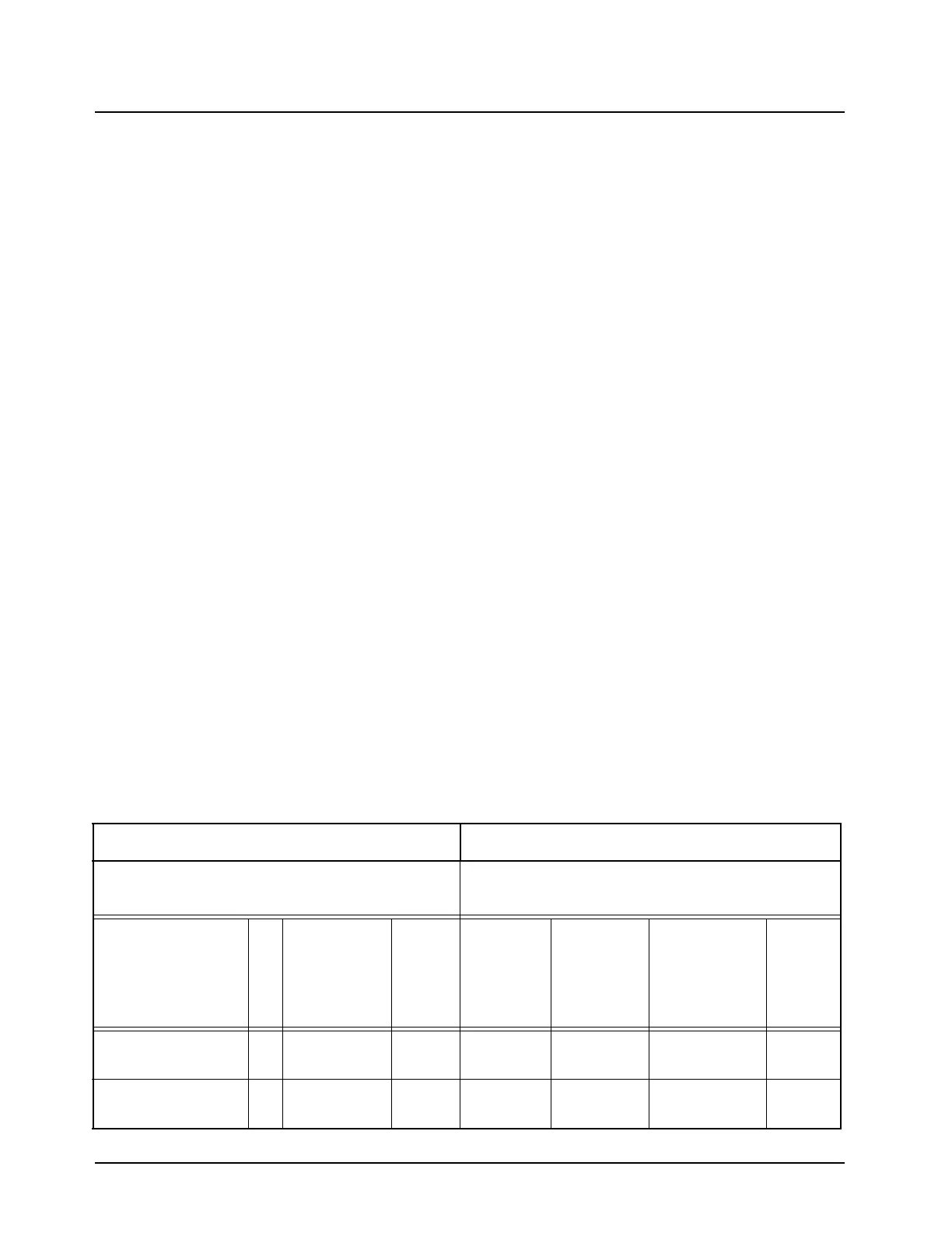
Table 7-1. Conventional/MDC/SmartNet/SmartZone Ignition Sense Function -
Operator Action vs Resultant Radio States
This Action During This State of Radio Causes The Following Radio States to Occur
Present State of Radio
Functions Available Through Ignition Sense
Programmed in RSS
Action
On
/
Off
Receive/
Stanby/
Emergency
Ignition
Blank
(Default
from
Factory
a
)
Soft Power
Off
Default
from
Factory
TX Inhibit
PTT
Inhibit
Press On/Off Button On Receive/
Standby
On Off Off Off Off
Press On/Off Button
b
On Emer On Off Off Off Off
 Loading...