MTS 793 Controller Hardware
FlexTest GT Controller Connections
152
Cabling and Using External Readout Devices
Cabled appropriately, your controller can send station signals to
external readout devices such as oscilloscopes and digital-volt-meters.
You define which signal is sent to the readout device using the Station
Setup window’s Readout panel.
Refer to “Working with Readout Devices” in the MTS 793 Control
Software manual for more information.
Station signal
diagram
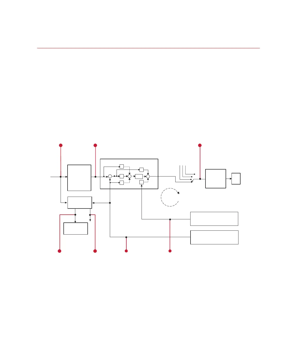
The block diagram identifies the station signals you can monitor.
Station signal
descriptions
Except for time and auxiliary data signals, station signals listed in your
software windows include the name of their associated control
channel. For example, if your channel is labeled Ch. 1, the available
station signals would be Ch.1 Output, Ch. 1 Command, and so forth.
Valve Driver Signals
Valve Drive
Command
Mode
Switch
P
I
D
F
-
-
S
-
FLF
PIDF Controller
Stabilizatio
Feedback
Signal
Active
Feedback
Signal
Absolute Error
Generator
Inner/Outer
Error Detector
from Other Modes of
this Channel
Signal
D/A
Output
Scalar
(convert control
signal to counts )
Stabilization
Output
Command
Compensator
Command
Closed
Loop
ErrorAbsolute Error
Sensor Signal
Test
Command
(Dela P/Load Cell Feedback)
Input Signal Conditioning
(LVDT Feedback)
Input Signal Conditioning
Artisan Technology Group - Quality Instrumentation ... Guaranteed | (888) 88-SOURCE | www.artisantg.com
 Loading...