Installing the 493.10 Chassis (FTGT)
MTS 793 Controller Hardware Installation
43
Setting I/O Carrier
module addresses
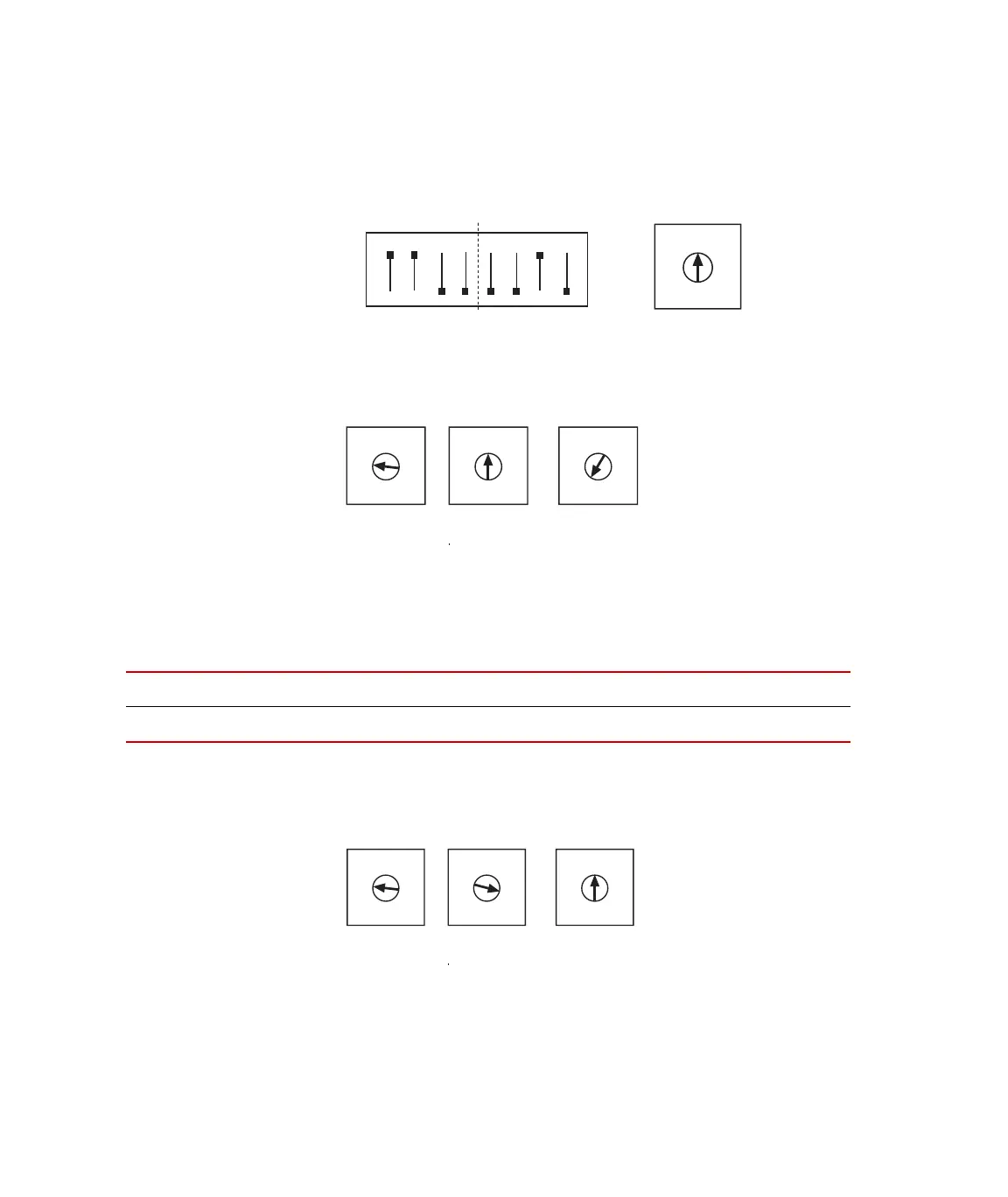
The dipswitch settings for address C20 is shown below. Increment the
rotary dipswitch as required to complete I/O Carrier module
addressing.
Setting GRES III
module addresses
The dipswitch settings for address C08 is shown below. Increment the
rotary dipswitch as required to complete GRES III module addressing.
Setting ADDA II
addresses
Use the onboard rotary dipswitches (S3, S2) and front panel rotary
dipswitch on each ADDA II module to set its address in accord with its
installed chassis slot as follows:
The rotary dipswitch settings for address C40 are shown below.
Increment the front panel dipswitch as required to complete ADDA II
module addressing.
1 2 3 4 5 6 7 8
ON
C
2
0
2
3
4
5
6
7
8
9
A
C
E
1F
S1
S2
0
2
3
4
5
6
7
8
9
A
C
E
1F
S2
0
2
3
4
5
6
7
8
9
A
C
E
1F
S3
0
2
3
4
5
6
7
8
9
A
C
E
1F
S1
SLOT
12345678910
ADDRESS
PPC PPC C40 C41 C42 C43 C44 C4A C4C
0
2
3
4
5
6
7
8
9
A
C
E
1F
S2
0
2
3
4
5
6
7
8
9
A
C
E
1F
S3
0
2
3
4
5
6
7
8
9
A
C
E
1F
On ADDA II
Front Panel
Artisan Technology Group - Quality Instrumentation ... Guaranteed | (888) 88-SOURCE | www.artisantg.com
 Loading...