Installing 497/498 Electronics (FTIIm)
MTS 793 Controller Hardware Installation
67
Jumper and switch
locations
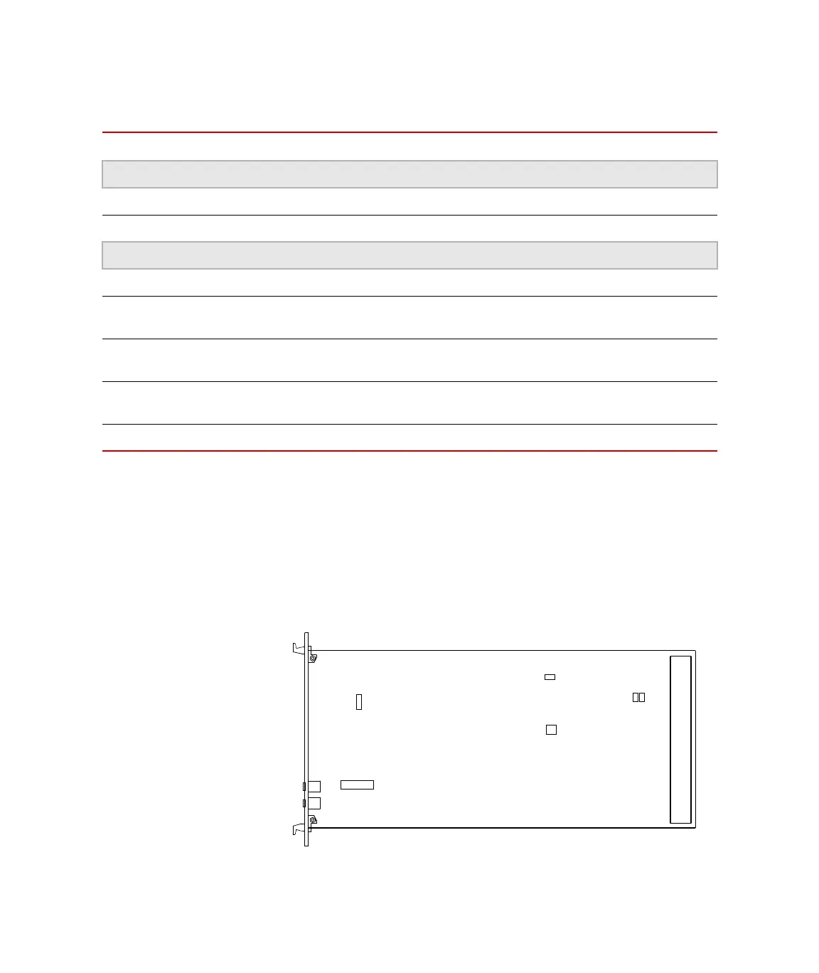
The following graphic illustrates the jumper locations on the 497.36
Communication Module.
Communication Modules Switch and Jumper Settings
C
HASSIS X1 SWITCH (S3) JUMPERS X1, X2, X3 JUMPER X5
*
* Jumper X5 is used for the RS-232 communications link (between the first chassis and the test
processor) and the RS-422 communications link (between the 497 communications modules in
each chassis).
For a single analog chassis:
497.01 Analog Chassis 1 Set to 1 Remove Install 3 and 4
497.05 Hydraulic Control Panel Set to
2 Install Install 1 and 2
For multiple analog chassis:
497.01 Analog Chassis 1 Set to 1 Remove Install 3 and 4
497.01 Analog Chassis 2
(optional)
Set to
2 Remove Install 3 and 4
497.01 Analog Chassis 3
(optional)
Set to
3 Remove Install 3 and 4
497.01 Analog Chassis 4
(optional)
Set to
4 Remove Install 3 and 4
497.05 Hydraulic Control Panel Set to
5
†
† The address switch on the hydraulic control panel should be set to the last number in the chassis
chain. For example, if you have a single 497.01 Analog Chassis, you should set the 497.05 Hydraulic
Control Panel address to 2; If you have two analog chassis, you should set it to 3, and so forth.
Install Install 1 and 2
Communication
Module Jumper
and Switch
Locations
4 1
3 2
X1
X5
X3 X2
S3
X4
X6
3
1
14 8
S4
S3
X10
X1
1 7
Artisan Technology Group - Quality Instrumentation ... Guaranteed | (888) 88-SOURCE | www.artisantg.com
 Loading...