MTS 793 Controller Hardware
Installing 497/498 Electronics (FTIIm)
Installation
64
Analog Chassis Transition Modules
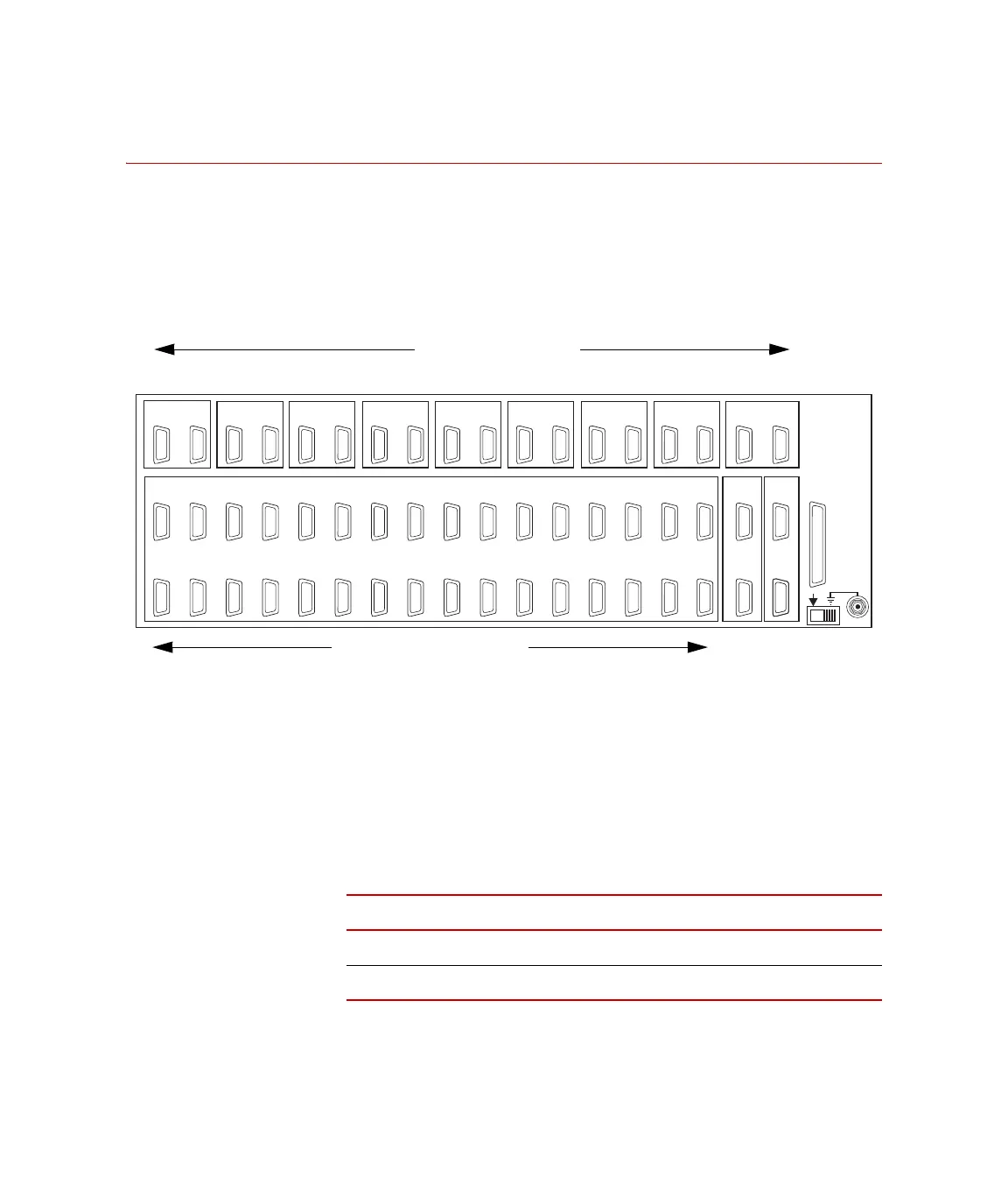
Transition modules located on the 497.01 rear panel provide signal
transfer between the 497 modules and external devices. One digital
transition module and up to eight analog transition modules can be
installed in this chassis. Each transition module plugs into the
backplane connectors and connects to two chassis slot locations.
How To Install a Transition Module
1. To install a transition module, remove the appropriate panel cover
from the analog chassis.
2. Plug the transition modules into the backplane connectors. Refer
the following table for transition module slot assignments.
3. Replace the panel cover and fasten the screw locks on all D
connectors.
J1602 J1502 J1402 J1302 J1202 J1102 J1002 J902 J802 J702 J602 J502 J402 J302
J202
J102
System
J1601 J1501 J1401 J1301 J1201 J1101 J1001 J901 J801 J701 J601 J501 J401 J301 J201 J101
J38
Aux
J28
I/O
J37
Aux
J27
I/O
J36
Aux
J26
I/O
J35
Aux
J25
I/O
J34
Aux
J24
I/O
J33
Aux
J23
I/O
J32
Aux
J22
I/O
J31
Aux
J21
I/O
J41
Com In
J42
Com Out
J43
XPTR In
J51
Intlk In
J50
DC Pwr
J44
XPTROut
J52
IntlkOut
16 15 14 13 12 11 10 9 8 7 6 5 4 3 2 1 A B
Chassis Slot Number
Analog Transition Modules Digital
Transition
Modules
Transition modules in the rear panel chassis
Slot Assignment
M
ODULE TYPE SLOT ASSIGNMENT
Analog Transition
1–2, 3–4, 5–6, 7–8, 9–10, 11–12, 13–14, 15-16
Digital Transition
A–B
Artisan Technology Group - Quality Instrumentation ... Guaranteed | (888) 88-SOURCE | www.artisantg.com
 Loading...