MTS 793 Controller Hardware
215
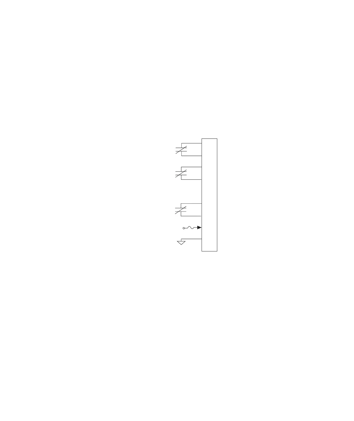
J55 Digital Outputs
Connector J55 Dig Out provides three general purpose digital outputs
that can send digital logic signals to external switches or logic devices.
• The digital output relays are rated for a maximum of 1 Amp max,
30 V DC/AC max.
• The outputs are optically isolated.
Cable specification The cabling information shown assumes a single cable destination
(with an overall shield). In other applications, the cable may have
more than one destination. For these applications an overall shield is
not practical and non-EMI connectors and back shells are permissible.
• 9 pin contact type D male EMI connector
• Back shell–EMI metallized plastic
• Cable–shielded twisted pairs as required (24 AWG minimum) with
drain wire(s) connected to the metallized backshell at the chassis.
Run/Stop setup If required, digital output 1 (pins 1 and 2) can be set up as a Run/Stop
connector. Use the following procedures to set up this Run/Stop
connector:
Relay Contact
Relay Contact
Relay Contact
To
External Device
J55
1
2
3
4
5
6
7
8
9
Channel 1 Output
Channel 2 Output
From
FT SE Controller
Channel 3 Output
+24 V
Artisan Technology Group - Quality Instrumentation ... Guaranteed | (888) 88-SOURCE | www.artisantg.com
 Loading...