Installing 497/498 Electronics (FTIIm)
MTS 793 Controller Hardware Installation
71
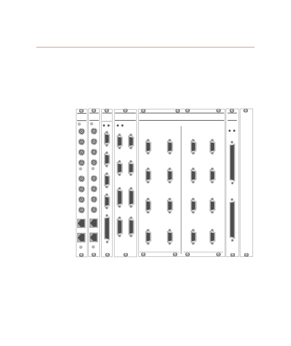
Test Processor Transition Modules
Transition modules are screwed into the back of the test processor
chassis. Each rear-panel transition module corresponds to a plug-in
module (or plug-in module mezzanine card) installed in the front of
the chassis.
Transition modules interface with the other test components via
connectors for external digital, analog, and communication cables.
J3C
Sta 3
Intlk
J4
497
Hyd
J6
I/O
J5
497
Intlk
J3D
Sta 4
Intlk
J3A
Sta 1
Intlk
J3B
Sta 2
Intlk
498
SYSTEM
DIGITAL I/O
498
DIGITAL I/O
TRANSITION
MODULE
J4 OUT
+5V +12V
J3 IN
J7
I/O
+5V +12V
1 - 2
DIGITAL I/O ACCESS PANEL
DIGITAL IN1-16
DIGITAL OUT1-16
Digital Input
Channels
3 - 4
5 - 6
7 - 8
9 - 10
11 - 12
13 - 14
15 - 16
1 - 2
3 - 4
5 - 6
7 - 8
9 - 10
11 - 12
13 - 14
15 - 16
Digital Output
Channels
J50A
J50B
J50C
498
RS-485
Transition
Module
J50D
J7
+12V +5V
J11
(CH 1-4)
J12
(CH 5-8)
498
ANALOG
OUT
CH 1
CH 2
CH 3
CH 4
CH 5
CH 6
CH 7
CH 8
J11
(CH 1-4)
J12
(CH 5-8)
498
INPUT
FILTER
CH 1
CH 2
CH 3
CH 4
CH 5
CH 6
CH 7
CH 8
Transition Modules (498.22 Chassis Rear Panel shown)
Artisan Technology Group - Quality Instrumentation ... Guaranteed | (888) 88-SOURCE | www.artisantg.com
 Loading...