ENGLISH – 9
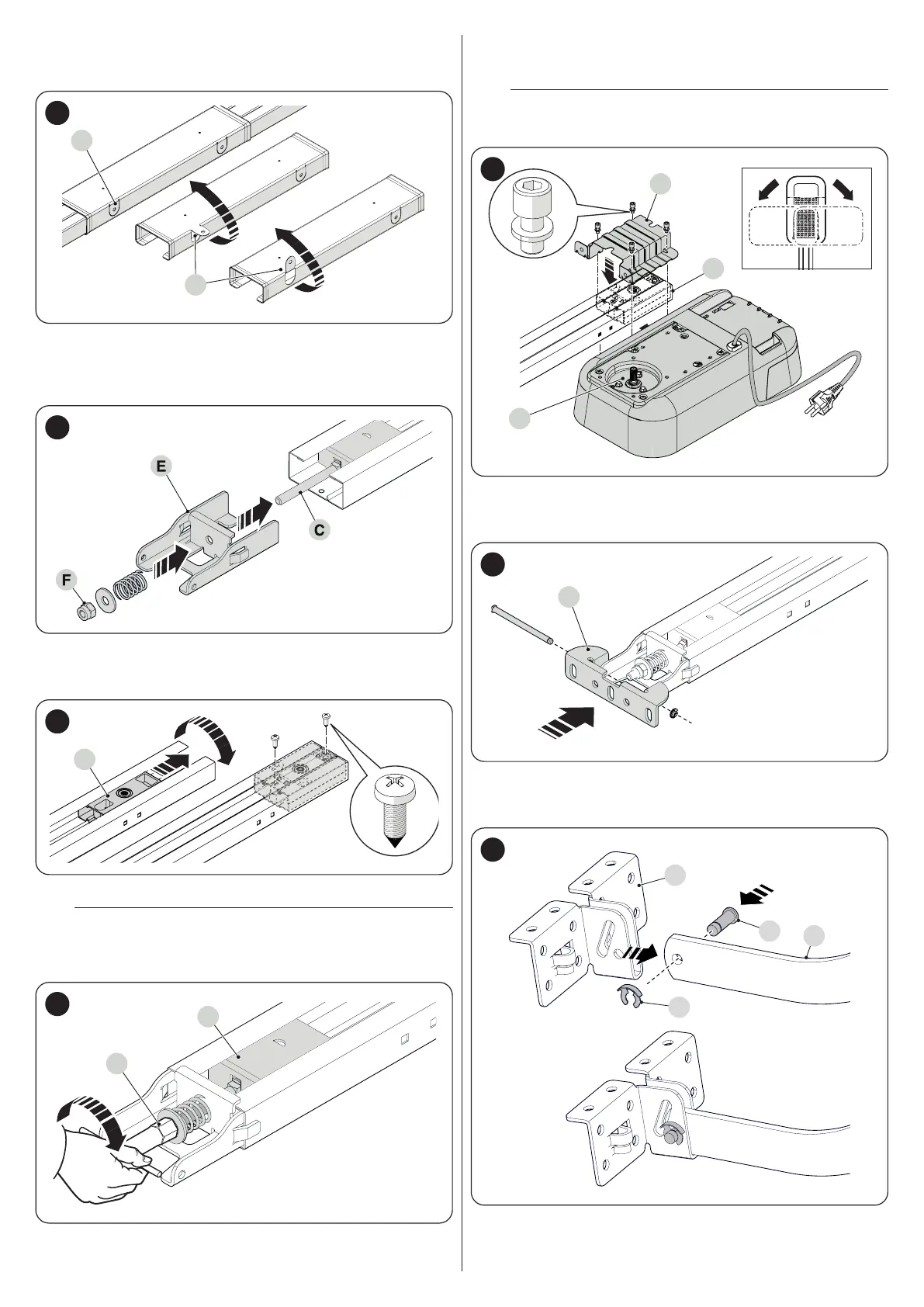
3. If the guide must be fastened in an intermediate position, it is pos-
sible to use the 4 tabs (C) present on the joining element.To do this,
simply turn the tabs by 90 or 180° (D) (“Figure 9")
C
D
9
4. insert the bracket (E) into the screw (C) and then make it slide inside
the guide
5. insert the spring, washer and nut (F) onto the screw (C) (“Figure
10")
10
6. slide the head (G) to the end of the guide
7. turn the guide over and lock the head (G) using the screws provided
(“Figure 11")
G
11
8. turn the nut (F) to tension the belt (“Figure 12")
a
An excessively taut belt could cause the gearmotor to
break, while an excessively slack belt could cause un-
pleasant noises.
F
E
12
9. insert the motor pin (H) into the head (G)
10. position the drawbar (I) and fasten it with the four screws (“Figure
13")
l
The motor can also be mounted at 90° with respect to the
guide axis.
G
I
H
13
11. from the opening side of the door, position the wall mounting brack-
et (J) on the guide and lock it by inserting the pin and cotter pin
(“Figure 14")
J
14
12. mount the door mounting bracket (K) on the drawbar (L)
13. insert the relevant pin (M) into the drawbar and lock it in place with
the cotter pin (N) (“Figure 15")
K
M
N
L
15
 Loading...


