4 Basic Operation
4 - 76
E5@C-T Digital Temperature Controllers User’s Manual (H185)
4-14 Customizing the PV/SP Display
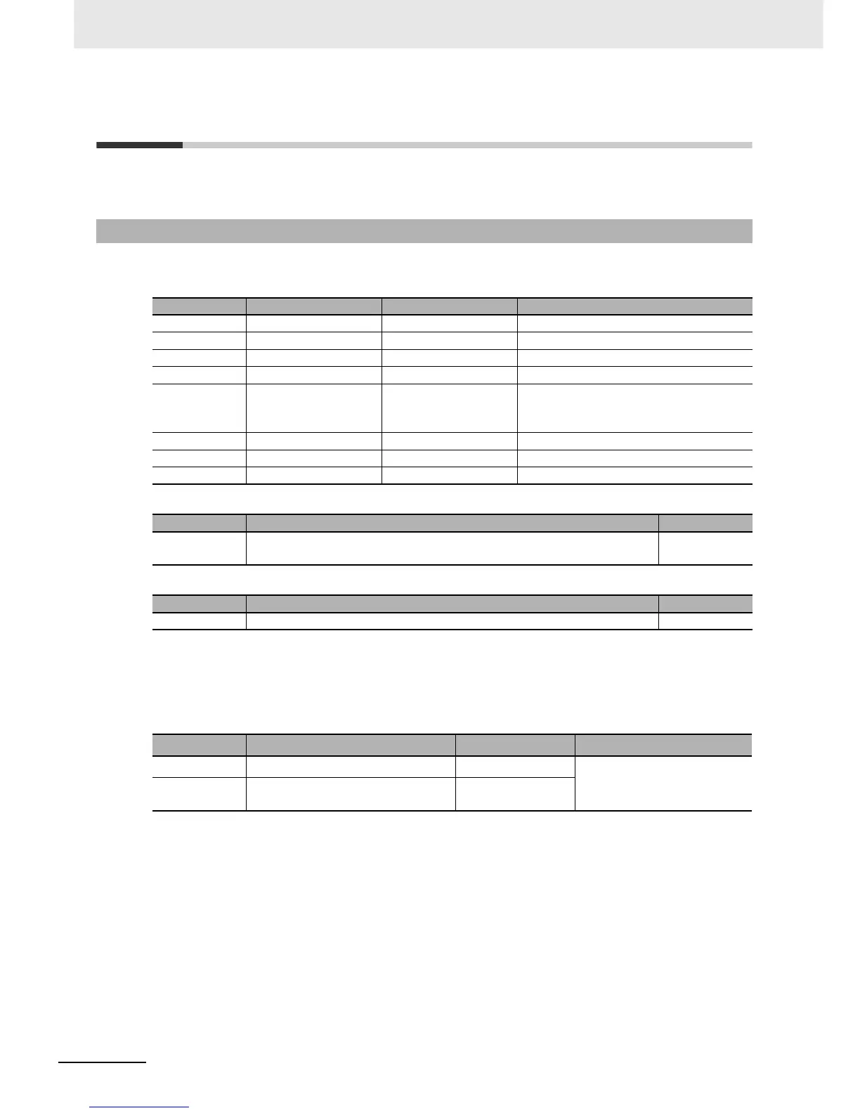
The following table shows the contents of the No. 1, 2, and 3 displays, according to the setting of the
PV/SP Display Screen Selection parameter.
The following table shows the contents of the No. 1, 2, and 3 displays, according to the setting of the
PV/SP Display Screen Selection parameter in the Advanced Function Setting Level.
During temperature input, the decimal point position depends on the currently selected sensor, and dur-
ing analog input it depends on the Decimal Point parameter setting.
PV/SP Display Selections
4-14-1 PV/SP Display Selections
Set value No. 1 display No. 2 display No. 3 display (E5EC-T/E5AC-T only)
0 Nothing is displayed. Nothing is displayed. Nothing is displayed.
1 PV SP Nothing is displayed.
2 PV Nothing is displayed. Nothing is displayed.
3 SP SP (character display) Nothing is displayed.
4 PV SP MV (heating)
(Valve opening for Position-proportional
Models)
5 PV SP MV (cooling)
6 PV SP Program number and segment number
7 PV SP Remaining segment time
Monitoring range Unit
PV
Temperature input: The specified range for the specified sensor.
Analog input: Scaling lower limit −5%FS to Scaling upper limit +5%FS
EU
Setting (monitoring) range Unit
SP SP lower limit to SP upper limit EU
Code Parameter Default Level
spd1 PV/SP No. 1 Display Selection 6 Advanced Function Setting
Level
spd2 PV/SP No. 2 Display Selection E5CC-T: 0
E5EC-T/E5AC-T: 7

 Loading...


