A - 5
A Appendices
E5@C-T Digital Temperature Controllers User’s Manual (H185)
A-1 Specifications
A
A-1-3 Program Controls
*1 The indication accuracy of K thermocouples in the −200 to 1,300°C range, T and N thermocouples at a temperature of
−100°C or less, and U and L thermocouples at any temperature is ±2°C ±1 digit maximum.
The indication accuracy of B thermocouples at a temperature of 400°C max. is not specified.
The indication accuracy of B thermocouples at a temperature of 400 to 800°C is ±3°C max.
The indication accuracy of R and S thermocouples at a temperature of 200°C max. is ±3°C±1 digit max.
The indication accuracy of W thermocouples is (±0.3% of PV or ±3°C, whichever is greater) ±1 digit max.
The indication accuracy of PLII thermocouples is (±0.3% of PV or ±2°C, whichever is greater) ±1 digit max.
*2 Ambient temperature: −10°C to 23°C to 55°C
Voltage range: −15% to +10% of rated voltage
*3 K thermocouple at −100°C max.: ±10°C max.
*4 The unit is determined by the setting of the Integral/Derivative Time Unit parameter.
*5 External serial communications (RS-485) and USB-Serial Conversion Cable communications can be used at the same
time.
Setup Tool ports
Top panel: An E58-CIFQ2 USB-Serial Conversion Cable is used to connect to a USB port
on the computer.
*5
Front panel (E5EC-T/E5AC-T): An E58-CIFQ2 USB-Serial Conversion Cable and
E58-CIFQ2-E Conversion Cable are used together to
connect a USB port on the computer.
*5
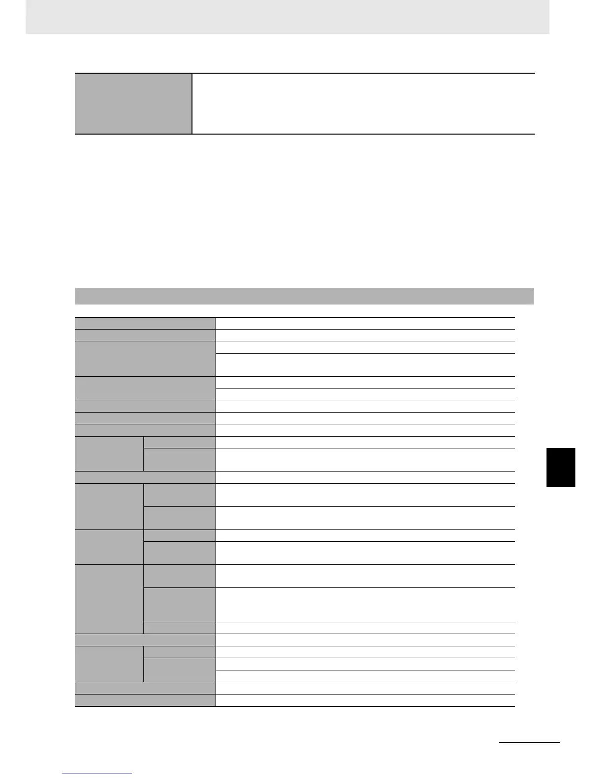
A-1-3 Program Controls
Number of programs (patterns) 8
Number of segments (steps) 32
Segment setting method
Step time programming (SP and time are set for each segment.)
Rate of rise programming (Segment format, SP, slope, and/or time are set for
each segment.)
Segment time
0 hr 0 min to 99 hr 59 min
0 min 0 s to 99 min 59 s
Alarm settings Alarms are set for each program.
Reset operation You can select either to stop control or use fixed SP control.
Startup operation You can select one of the following: Continue, reset, run, or Manual Mode.
PID sets
Number of sets 8 sets
Setting method
A PID set is specified for each program. (Automatic PID set selection is also
possible.)
Alarm SP selection You can select from the ramp SP or target SP.
Program status
control
Segment
operation
Advance, segment jump, hold, and wait
Program
operation
Repeating and linking programs
Waiting
Wait method At the end of segments
Wait band
setting
The same wait band is used for the entire program.
Time signals
Number of
outputs
2
Number of
ON/OFF
operations
One time per output
Setting method Time signals are set for each program.
Program status output Program end output (settable pulse width), RUN output, and stage output
Program
startup
operation
PV start You can select an SP start or an PV start with slope priority.
Standby
0 hr 0 min to 99 hr 59 min
0 days, 0 hr to 99 days 23 hr
Operation end operation You can select from the following: reset, continue, and Fixed SP Mode.
Program SP shift The same program SP shift is used for the entire program.

 Loading...


