5 - 77
5 Advanced Operations
E5@C-T Digital Temperature Controllers User’s Manual (H185)
5-20 Displaying PV/SV Status
5
5-20-1 PV and SV Status Display Functions
5-20 Displaying PV/SV Status
z PV Status Display Function (Advanced Function Setting Level)
The PV on the No. 1 display in the PV, PV/SP, PV/Manual MV, or PV/SP Manual MV Display and the
control or alarm status specified for the PV status display function are alternately displayed in 0.5-s
cycles.
• PV
• PV/SP*
• PV/Manual MV (Valve Opening)
• PV/SP/Manual MV (Valve Opening)
* This includes when the PV/SP is selected for the Monitor/Setting Item parameter.
Note: The default is OFF.
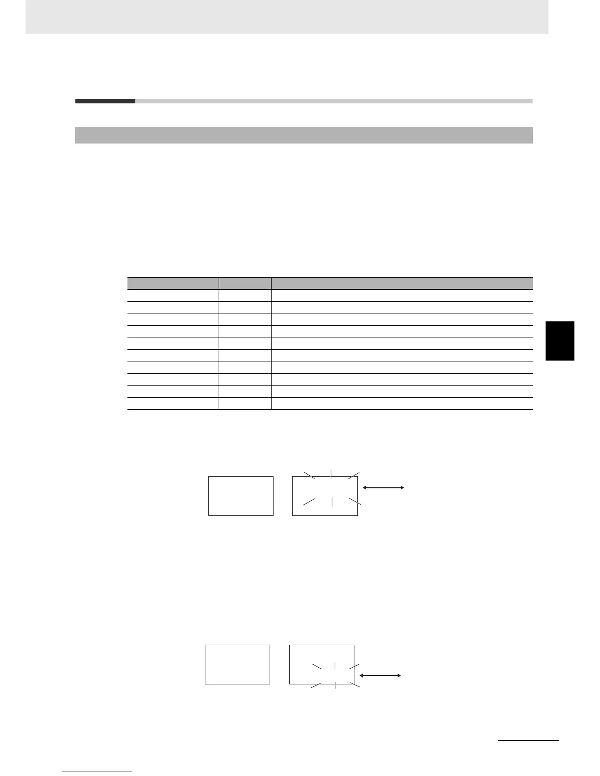
Example: When RST Is Selected for the PV Status Display Function
z SV Status Display Function (Advanced Function Setting Level)
The SP, Manual MV, or blank on the No. 2 display in the PV/SP, PV, or PV/Manual MV Display and
the control or alarm status specified for the SV status display function are alternately displayed in
0.5-s cycles.
The set values are the same as for PV Status Display Function.
Example: When ALM1 Is Selected for the SV Status Display Function
5-20-1 PV and SV Status Display Functions
Set value Display Function
OFF off No PV status display
Manual manu MANU is alternately displayed during manual control.
Reset rst RST is alternately displayed while operation is in reset status.
Alarm 1 alm1 ALM1 is alternately displayed during Alarm 1 status.
Alarm 2 alm2 ALM2 is alternately displayed during Alarm 2 status.
Alarm 3 alm3 ALM3 is alternately displayed during Alarm 3 status.
Alarm 4 alm4 ALM4 is alternately displayed during Alarm 4 status.
Alarm 1 to 4 OR status alm ALM is alternately displayed when Alarm 1, 2, 3, or 4 is set to ON.
Heater Alarm ha HA is alternately displayed when an HB alarm or HS alarm is ON.
Standby stb STB is alternately displayed while operation is on standby.
25
100
rst
100
25
Normal
PV/SP
When Run/Reset Parameter
Is Reset
Alternating
display
100
alm1
25
100
25
When ALM1 Is ON
Normal
PV/SP
Alternating
display

 Loading...


