A - 33
A Appendices
E5@C-T Digital Temperature Controllers User’s Manual (H185)
A-6 Parameter Operation Lists
A
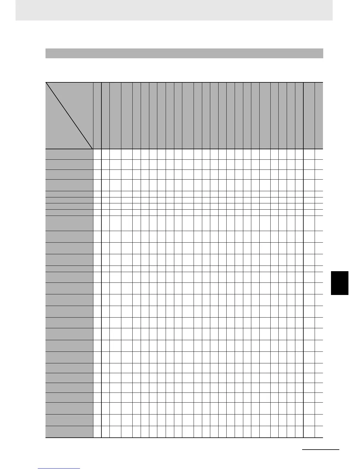
A-6-11 Initialization According to Parameter Changes
The parameters that are initialized when parameters are changed are shown under Related initialized
parameters.
A-6-11 Initialization According to Parameter Changes
Input Type
Temperature Unit
Scaling Lower Limit
Scaling Upper Limit
SP Lower Limit
SP Upper Limit
PID ON/OFF
Standard or Heating/Cooling
Transfer Output Type
Close/Floating
RT
PID Set Automatic Selection Data
Direct Setting of Position
Proportional MV
Integral/Derivative Time Unit
Alarm 1 Type
Alarm 2 Type
Alarm 3 Type
Alarm 4 Type
Program Time Unit
Startup Operation
Operation End Operation
Step Time/Rate of
Rise Programming
Time Unit of Ramp Rate
Reset Operation
Standby Time Unit
Heating/Cooling Tuning Method
Password to Move
to Protect Level
Run/Reset
SP Upper Limit
SP Lower Limit
z
*1
z
*1
z
*1
--- --- --- --- --- --- --- --- --- --- --- --- --- --- --- --- --- ---| --- --- --- --- ---
Segment SP
z
*2
z
*2
z
*2
z
*2
--- --- --- --- --- --- --- --- --- --- --- --- --- --- --- --- --- --- --- --- --- ---
RT
z
*3
--- --- --- --- --- --- --- --- --- --- --- --- --- --- --- --- --- --- --- --- --- --- --- --- ---
Integral/Derivative
Time Unit
--- --- --- --- --- --- --- --- z
*9
--- --- --- --- --- --- --- --- --- --- --- --- --- --- --- --- ---
MV at Reset --- --- --- --- --- z --- z --- --- z --- --- --- --- --- --- --- --- --- --- --- --- --- --- ---
MV at PV Error --- --- --- --- --- z --- z --- --- z --- --- --- --- --- --- --- --- --- --- --- --- --- --- ---
Manual MV --- --- --- --- --- --- --- z --- --- z --- --- --- --- --- --- --- --- --- --- --- --- --- --- ---
Manual MV Initial Value z
Transfer Output Upper
Limit, Transfer Output
Lower Limit
z
*4.2
z
*4.2
z
*4.2
z
*4.1
--- z
*4.3
z
*4.4
--- --- --- --- --- --- --- --- --- --- --- --- --- --- --- --- --- --- ---
SP Mode
--- --- --- --- --- --- --- --- --- --- --- --- --- --- --- --- --- --- --- --- --- z
*11
--- --- --- ---
Fixed SP
z
*2
z
*2
z
*2
z
*2
--- --- --- --- --- --- --- --- --- --- --- --- --- --- --- --- --- --- --- --- --- ---
All PID AT Upper Limit
SP
z
*8
z
*8
z
*8
z
*8
--- --- --- --- --- --- --- --- --- --- --- --- --- --- --- --- --- --- --- --- --- ---
Standby Time --- --- --- --- --- --- --- --- --- --- --- --- --- --- --- --- --- --- --- --- --- --- z --- --- ---
Control Output 1
Assignment
--- --- --- --- --- z --- --- --- --- --- --- --- --- --- --- --- --- --- --- --- --- --- --- --- ---
Control Output 2
Assignment
--- --- --- --- --- z
*6
--- --- --- --- --- --- --- --- --- --- --- --- --- --- --- --- --- --- --- ---
Auxiliary Output 1
Assignment
--- --- --- --- --- z
*7
--- --- --- --- --- --- --- --- --- --- --- --- --- --- --- --- --- --- --- ---
Auxiliary Output 2
Assignment
--- --- --- --- --- z
*6
--- --- --- --- --- --- --- --- --- --- --- --- --- --- --- --- --- --- --- ---
Auxiliary Output 3
Assignment
--- --- --- --- --- z --- --- --- --- --- --- --- --- --- --- --- --- --- --- --- --- --- --- --- ---
Auxiliary Output 4
Assignment
--- --- --- --- --- z
*6
--- --- --- --- --- --- --- --- --- --- --- --- --- --- --- --- --- --- --- ---
Move to Protect Level
--- --- --- --- --- --- --- --- --- --- --- --- --- --- --- --- --- --- --- --- --- --- --- --- z
*10
---
Position Proportional
Dead Band
--- --- --- --- --- --- --- z
*20
--- --- --- --- --- --- --- --- --- --- --- --- --- --- --- --- --- ---
Dead Band
z
*13
--- --- --- --- --- --- --- --- --- --- --- --- --- --- --- --- --- --- --- --- --- --- --- --- ---
Hysteresis (Heating)
z
*13
--- --- --- --- --- --- --- --- --- --- --- --- --- --- --- --- --- --- --- --- --- --- --- --- ---
Hysteresis (Cooling)
z
*13
--- --- --- --- --- --- --- --- --- --- --- --- --- --- --- --- --- --- --- --- --- --- --- --- ---
Wait Band
z
*13
--- --- --- --- --- --- --- --- --- --- --- --- --- --- --- --- --- --- --- --- --- --- --- --- ---
Alarm 1 Hysteresis
z
*14
--- --- --- --- --- --- --- --- --- --- --- z
*15
--- --- --- --- --- --- --- --- --- --- --- --- ---
Alarm 2 Hysteresis
z
*14
--- --- --- --- --- --- --- --- --- --- --- --- z
*15
--- --- --- --- --- --- --- --- --- --- --- ---
Alarm 3 Hysteresis
z
*14
--- --- --- --- --- --- --- --- --- --- --- --- --- z
*15
--- --- --- --- --- --- --- --- --- --- ---
Changed
parameter
Related
initialized
parameters

 Loading...


