7 - 7
7 User Calibration
E5@C-T Digital Temperature Controllers User’s Manual (H185)
7-4 Resistance Thermometer Calibration
7
7-4 Resistance Thermometer Calibration
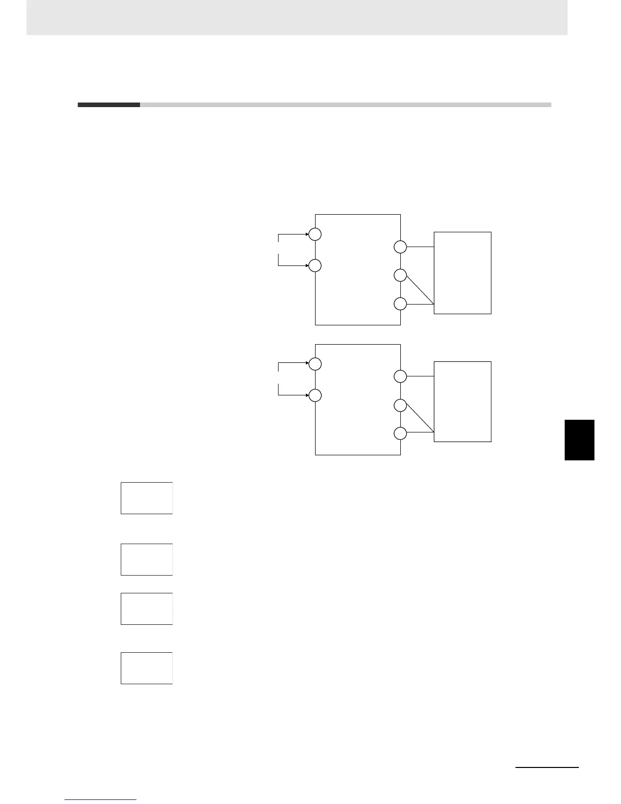
In this example, calibration is shown for Controller with a resistance thermometer set as the input type.
Use connecting wires of the same thickness
1. Connect the power supply.
2. Connect a precision resistance box (called a "6-dial variable resistor" in this
manual) to the resistance thermometer input terminals, as shown in the following
diagram.
3. Turn the power ON.
4. Move to the Calibration Level.
This starts the 30-minute aging timer. This timer provides an approximate timer for
aging. After 30 minutes have elapsed, the No. 2 display changes to 0. You can
advance to the next step in this procedure even if 0 is not displayed.
• Input type 0:
• Input types 1, 2, 3, 4:
5. Execute calibration for the main input.
Press the M Key to display the count value for each input type.
The No. 2 display at this time shows the currently entered count value in
hexadecimal. Set the 6-dial as follows:
•
Input type 0: 390 Ω
• Input type 1, 2, 3 or 4: 280 Ω
Allow the count value on the No. 2 display to fully stabilize, then press the D Key to
temporarily register the calibration settings.
If this count value is outside of the specified range, the No. 2 display will flash and
the count value will not be temporarily registered.
6. When the M Key is pressed, the status changes as shown to the left.
Set the 6-dial to 10 Ω.
Allow the count value on the No. 2 display to fully stabilize, then press the D Key
to temporarily register the calibration settings.
If this count value is outside of the specified range, the No. 2 display will flash and
the count value will not be temporarily registered.
A
6-dial variable
resistor
4
5
B'
B
6
Input power supply
11
12
E5CC-T
A
6-dial variable
resistor
22
23
B'
B
24
Input power supply
1
2
E5EC-T/AC-T
adj
30
p390
e20c
p280
e26b
p 10
4543

 Loading...


