6 - 83
6 Parameters
E5@C-T Digital Temperature Controllers User’s Manual (H185)
6-10 Advanced Function Setting Level
6
rest
Standby Sequence Reset Alarm 1 to 4 type must be 5, 6, 7, 10, or 11.
• This parameter selects the conditions for enabling reset after the standby sequence of the
alarm has been canceled.
• Output is turned OFF when switching to the Initial Setting Level, Communications Setting
Level, Advanced Function Setting Level, or Calibration Level.
• Condition A
At the Start of Operation (including Power ON)
When the Run/Reset parameter is changed to Run.
When program is started (including when the program is started for program repetition or
link).
When the segment is changed (including when an advance is executed).
When the program number is changed.
When the SP of the current segment is changed (including changing the fixed SP in Fixed
SP Mode).
When an alarm value (alarm upper or lower limit) is changed in the current program.
When the PV input shift or PV slope coefficient value is changed.
When the program SP shift value is changed.
• Condition B
Power ON
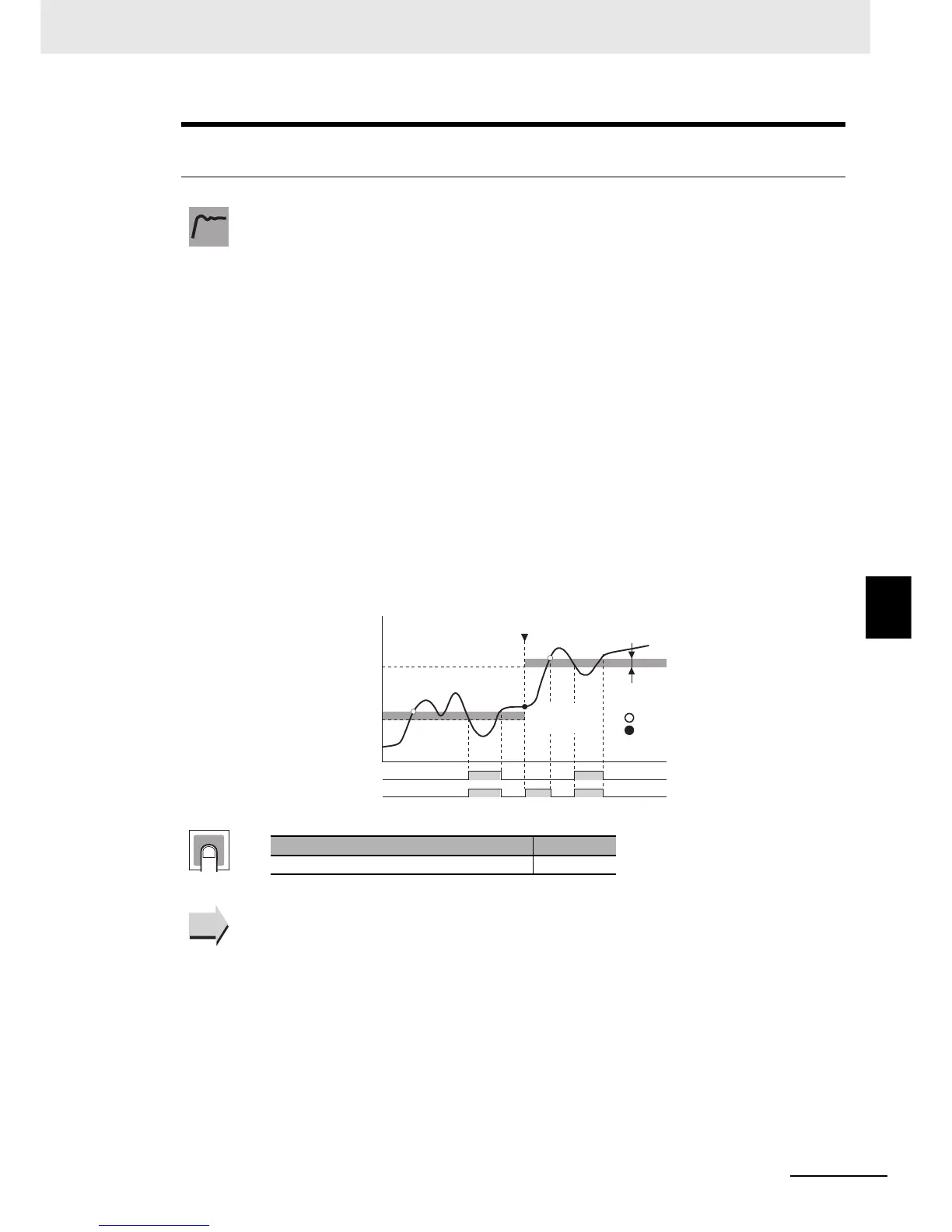
The following example shows the reset operation when the alarm is a lower-limit alarm
with a standby sequence.
z Related Parameters
Alarm 1 to 4 Type (Initial Setting Level): Page 6-66
Alarm 1 to 4 Latch (Advanced Function Setting Level): Page 6-89
Function
Alarm
(after change)
Alarm
SP change
Condition A only
Alarm hysteresis
: Standby sequence canceled
: Standby sequence reset
Alarm output:
Condition A
Alarm output:
Condition B
Condition A
only
Setting
Setting range Default
a: Condition A, b: Condition B a
See
See

 Loading...


