6 Incremental Encoder Input Units
6 - 14
NX-series Position Interface Units User’s Manual (W524)
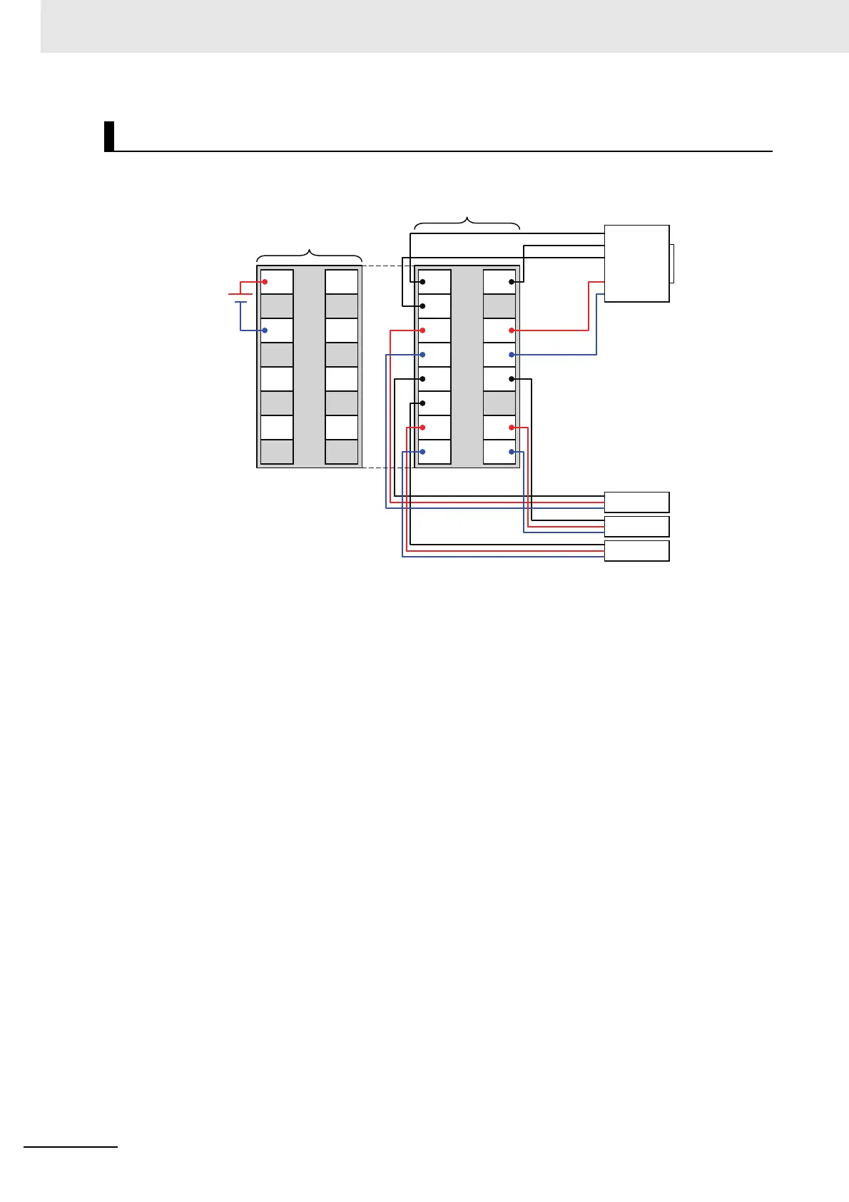
The following is a wiring example.
Note 1. The encoder and external inputs on Units with voltage inputs are PNP connections.
2. To supply power to connected external devices, connect an 24-VDC I/O power supply to the Communi-
cations Coupler Unit or an Additional I/O Power Supply Unit to supply power to the Incremental Encoder
Input Unit.
Wiring Example
A
Z
IOV
IOG
I0
I2
B
NC
IOV
IOG
I1
NC
IOV
IOV
IOG
IOG
IOV
IOV
IOG
IOG
IOG IOG
IOV IOV
I/O power
supply (24 VDC)
Additional I/O Power
Supply Unit
Incremental Encoder Input Unit
Sensor 1
Sensor 2
Sensor 3
Encoder

 Loading...


