7 - 7
7 SSI Input Units
NX-series Position Interface Units User’s Manual (W524)
7-4 Part Names and Functions
7
7-4-1 Parts and Names
7-4 Part Names and Functions
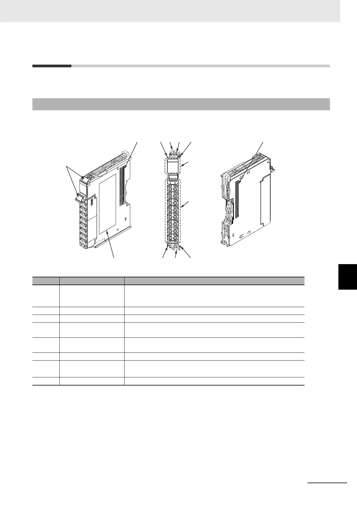
This section describes the names and functions of the parts of the SSI Input Units.
The names of the parts of the NX-ECS112 and NX-ECS212 are shown in the following figure.
7-4-1 Parts and Names
Symbol Name Function
(A) Marker attachment loca-
tions
This is where the markers are attached. OMRON markers are
pre-installed at the factory. You can also install commercially available
markers.
(B) NX bus connector This connector is used to connect to another Unit.
(C) Unit hookup guides These guides are used to connect two Units to each other.
(D) DIN Track mounting
hooks
These hooks are used to mount the NX Unit to a DIN Track.
(E) Protrusions for removing
the Unit
These protrusions are to hold onto when you need to pull out the Unit.
(F) Indicators The indicators show the current operating status of the Unit.
(G) Terminal block The terminal block is used to connect to external devices.
The number of terminals depends on the Unit.
(H) Unit specifications The specifications of the Unit are given here.
(C)(D)
(H)
(G)
(F)
(C)
(A)
(E)
(C)(E)
(C)
(B)
(B)

 Loading...


