8 Pulse Output Units
8 - 4
NX-series Position Interface Units User’s Manual (W524)
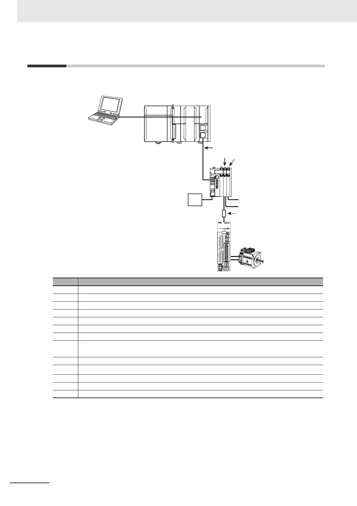
8-2 System Configuration
The following figure shows the system configuration of a Pulse Output Unit.
Symbol Description
(A) Support Software (Sysmac Studio)
(B) Connection to the peripheral USB port or built-in EtherNet I/P port on an NJ/NX-series CPU Unit
(C) EtherCAT master (NJ/NX-series CPU Unit)
(D) EtherCAT communications cable
(E) EtherCAT Coupler Unit
(F) Pulse Output Unit
(G) Digital Input Unit
(H)
External inputs
*1
(positive limit input, negative limit input, home proximity input, and immediate stop
input)
*1. When the Unit is connected to an NJ/NX-series CPU, you can use these inputs by adding a Digital Input Unit
and assigning MC Function Module functions. For information on Digital Input Units, refer to the NX-series
Digital I/O Units User’s Manual (Cat. No. W521).
(I) Latch inputs (Latch input 1 and latch input 2)
(J)
Current-limiting resistor
*2
*2. The pulse output from a Pulse Output Unit is a 24-VDC open collector output. Connect an external current-lim-
iting resistor according to the input specifications of the connected motor drive.
Example: For a G5-series Servo Drive, connect a 2-kΩ (1/2-W) resistor in series.
(K) Drive with pulse string input
(L) Motor
(M) I/O power supply
(E)
(A)
(B)
(D)
(C)
(F)
(M)
(H)
(I)
(J)
(G)
(L)
(K)

 Loading...


