6 Incremental Encoder Input Units
6 - 34
NX-series Position Interface Units User’s Manual (W524)
6-7 I/O Data Specifications
This section describes the data items that you can allocate to I/O, the data configurations, and the axis
settings.
You can allocate the following 15 data items to the I/O for an Incremental Encoder Input Unit.
The data items are described in the following sections.
• If you use an EtherCAT Coupler Unit, you can use the Read NX Unit Object instruction or the
Write NX Unit Object instruction to access data that is not assigned as I/O. Refer to the
NJ/NX-series Instructions Reference Manual (Cat. No. W502) for details on the Read NX
Unit Object instruction or the Write NX Unit Object instruction.
For the index numbers, refer to A-2-2 Incremental Encoder Input Units on page A-29.
• If you use an EtherNet/IP Coupler Unit, you cannot access data that is not assigned to I/O.
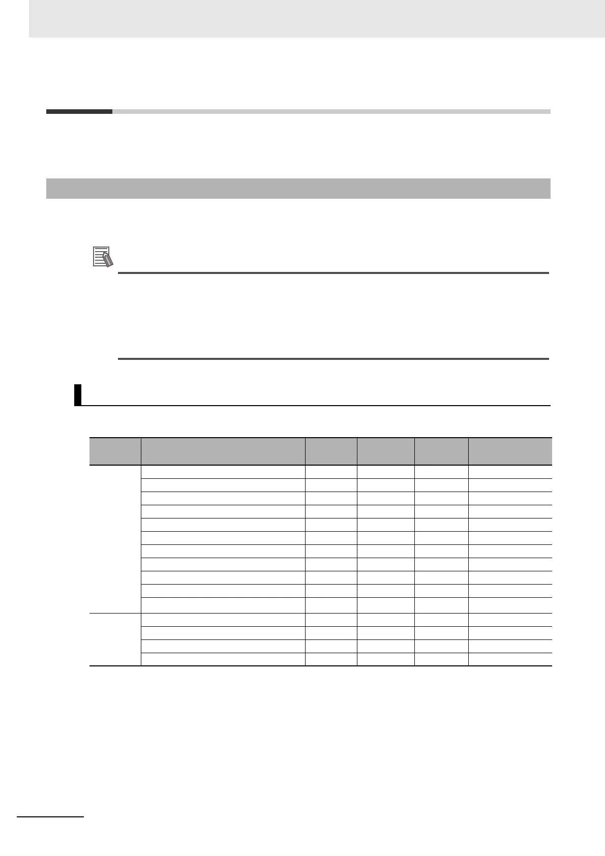
The data items that you can allocate to I/O for a One-input Unit are listed in the following table.
6-7-1 Data Items for Allocation to I/O
NX-EC0112, NX-EC0122, NX-EC0132, and NX-EC0142
Area Data item
Size
(bytes)
Data type
Default
*1
*1. The Default column shows the data item that are set when the Unit is shipped from the factory. You can allocate
other data items.
MC Function
Module PDO
*2
*2. These PDOs are required to use the MC Function Module.
Input Encoder Counter Status 1 BYTE Yes
Reset/External Input Status 1 BYTE Yes
Encoder Present Position 4 DINT Yes Yes
Pulse Period Measurement Status 1 BYTE Yes
Latch Status 2 WORD Yes Yes
Latch Input 1 Data 4 DINT Yes Yes
Latch Input 2 Data 4 DINT Yes Yes
Internal Latch Data 4 DINT
Pulse Rate 4 UDINT
Pulse Period Measured Value 4 UDINT
Time Stamp
*3
*3. An EtherCAT Coupler Unit with unit version 1.1 or later is required.
8ULINT
Output Encoder Counter Operation Command 2 WORD
Pulse Period Measurement Function 2 WORD Yes
Latch Function 2 WORD Yes Yes
Preset Command Value 4 DINT

 Loading...


