8 - 13
8 Pulse Output Units
NX-series Position Interface Units User’s Manual (W524)
8-5 Part Names and Functions
8
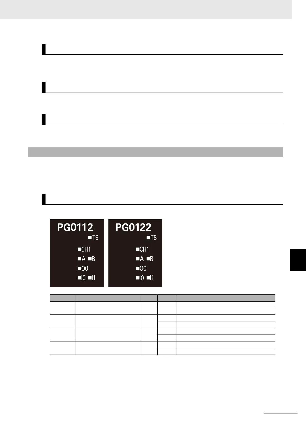
8-5-3 Indicators
The indicators show the Unit status, pulse output operation status, external I/O status, and other infor-
mation.
The terminal block is used to connect the external I/O signals.
The bus connectors connect the Units to each other.
This section describes the indicators on the Pulse Output Unit.
Refer to 3-2 Indicators on page 3-3 for information on the indicators that are provided on all Position
Interface Units.
The indicators for a One-input Unit are described in the following table.
Indicators
Terminal Block
NX Bus Connector
8-5-3 Indicators
NX-PG0112 and NX-PG0122
Indicator Name Color Status Description
CH Pulse output status indicator Green Lit Ready for pulse output.
Not lit Not ready for pulse output.
A and B Pulse output indicators Yellow Lit Phase-A or phase-B output is active.
Not lit Phase-A or phase-B output is not active.
I0 and I1 External input status indica-
tors
Yellow Lit The corresponding external input is ON.
Not lit The corresponding external input is OFF.
O0 External output status indica-
tor
Yellow Lit The external output is ON.
Not lit The external output is OFF.

 Loading...


