7 SSI Input Units
7 - 38
NX-series Position Interface Units User’s Manual (W524)
7-9 Functions
This section describes the SSI data settings and other functions, such as the coding methods and bit
shifting.
Precautions for Correct Use
Functions are restricted by the selected I/O refreshing method and Controller. Refer to 7-6-5
Differences in I/O Refreshing Methods Based on the Controller on page 7-21 for details.
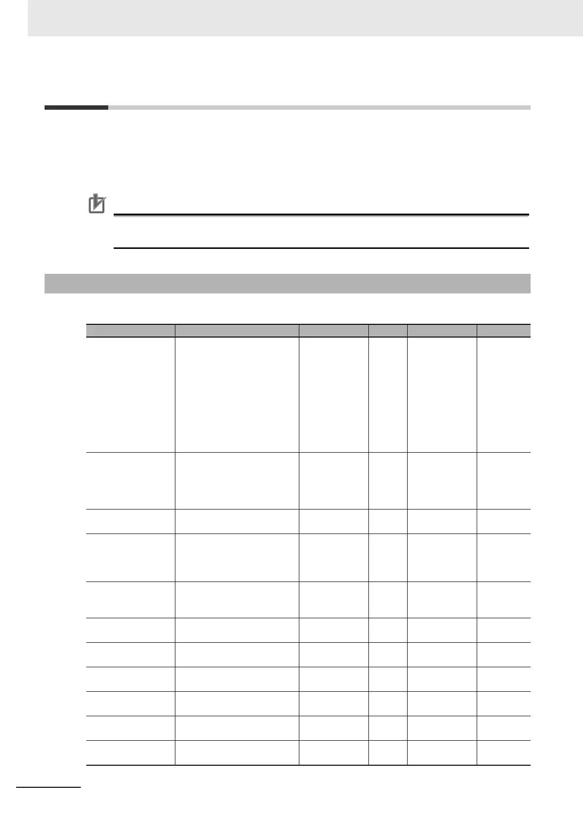
The following table lists the parameters that are used in the SSI Input Units.
7-9-1 Parameters
Parameter name Function Setting range Unit Default Reference
Baud Rate 0: 100 kHz
1: 200 kHz
2: 300 kHz
3: 400 kHz
4: 500 kHz
5: 1.0 MHz
6: 1.5 MHz
7: 2.0 MHz
0 to 7 --- 4 P. 7-41
SSI Communica-
tions Start-Up Time
0: 2,000 ms
1: 1,050 ms
2: 500 ms
3: No delay
0 to 3 0 P. 7-41
Wait Time for
Receive Enabled
This is the wait time until the
next frame can be sent.
0 to 9999 10 μs0 P. 7-41
Monoflop Time This is the duration from
when the last block is sent
until the high level is con-
firmed on the data line.
1 to 9999 10 μs4 P. 7-41
Conversion Wait
Time
This is the wait time from the
falling edge of the first clock
signal to the rising edge.
0 to 64 --- 0 P. 7-41
Valid Data Length This is the valid bit length of
the SSI data.
1 to 32 Bits 25 P. 7-41
Single-turn Data
Start Bit
This is the start bit position for
single-turn data.
0 to 31 Bits 12 P. 7-41
Single-turn Data
Length
This is the data length of sin-
gle-turn data.
0 to 32 Bits 13 P. 7-41
Multi-turn Data Start
Bit
This is the start bit position for
multi-turn data.
0 to 31 Bits 0 P. 7-42
Multi-turn Data
Length
This is the data length of
multi-turn data.
0 to 32 Bits 12 P. 7-42
Status Data Start Bit This is the start bit position for
status data.
0 to 31 Bits 0 P. 7-42

 Loading...


