6 - 13
6 Incremental Encoder Input Units
NX-series Position Interface Units User’s Manual (W524)
6-5 Terminal Block Arrangement
6
6-5-2 NX-EC0122
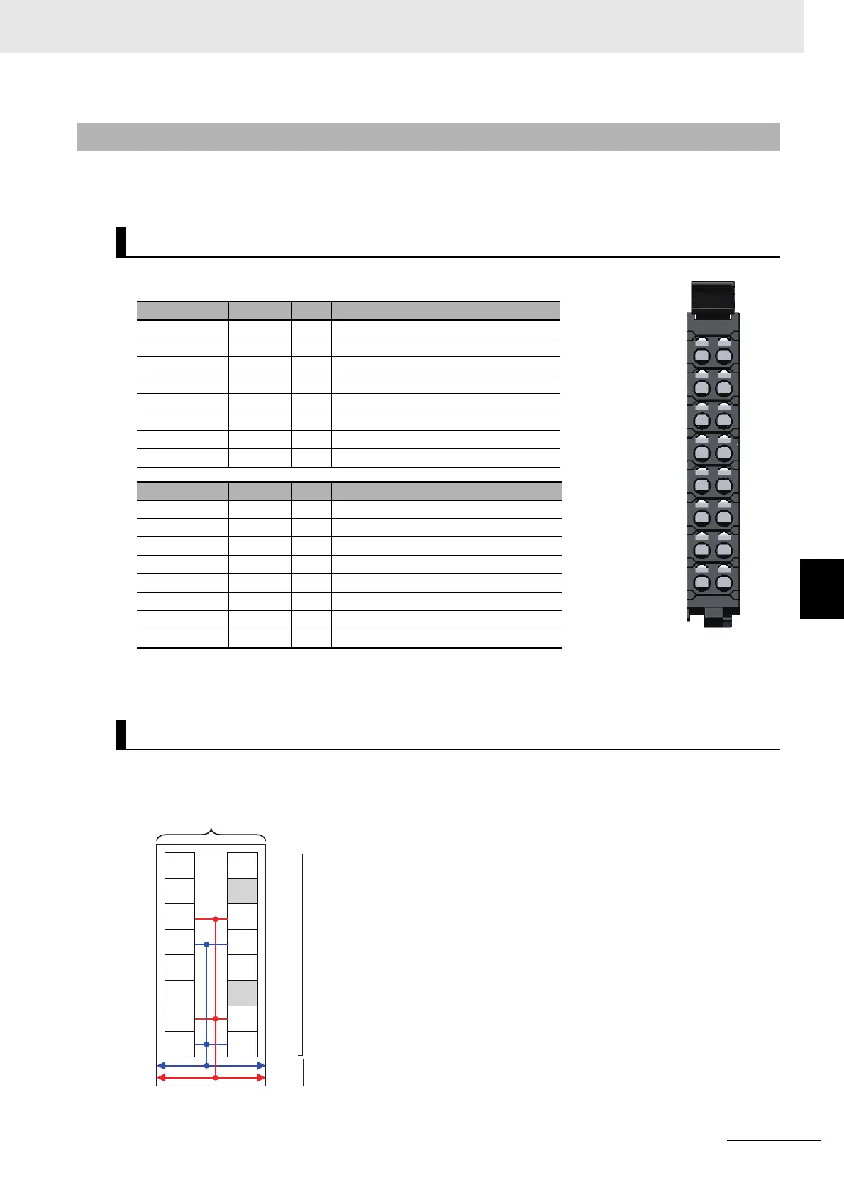
This section provides diagrams of the terminal block arrangement and internal power supply wiring of
the NX-EC0122. It also provides a wiring example.
A 16-terminal terminal block is used.
Note The encoder power supply output (24 V and 0 V) is provided power from the I/O power supply connected to
the Communications Coupler Unit or an Additional I/O Power Supply Unit.
The following diagram shows the internal power supply wiring.
6-5-2 NX-EC0122
Terminal Block Arrangement
Terminal No. Symbol I/O Name
A1 A I Counter input A
A2 Z I Counter input Z
A3 IOV O Encoder power supply output, 24 V
A4 IOG O Encoder power supply output, 0 V
A5 I0 I External input 0
A6 I2 I External input 2
A7 IOV O Encoder power supply output, 24 V
A8 IOG O Encoder power supply output, 0 V
Terminal No. Symbol I/O Name
B1 B I Counter input B
B2 NC --- Not used.
B3 IOV O Encoder power supply output, 24 V
B4 IOG O Encoder power supply output, 0 V
B5 I1 I External input 1
B6 NC --- Not used.
B7 IOV O Encoder power supply output, 24 V
B8 IOG O Encoder power supply output, 0 V
Internal Power Supply Wiring Diagram
A
Z
IOV
IOG
I0
I2
IOV
IOG
B
NC
IOV
IOG
I1
NC
IOV
IOG
A B
A B
1 1
2 2
3 3
4 4
5 5
6 6
7 7
8 8
Terminal block
NX bus connecto
A
Z
IOV
IOG
I0
I2
IOG
B
NC
IOV
IOG
I1
NC
IOG
IOV IOV
24 V
0 V
Incremental Encoder
Input Unit
Note The I/O power is supplied from the I/O power supply con-
nected to the I/O power supply terminals on the Communica-
tions Coupler Unit or an Additional I/O Power Supply Unit.

 Loading...


