6 Incremental Encoder Input Units
6 - 80
NX-series Position Interface Units User’s Manual (W524)
Precautions for Correct Use
To satisfy the specifications for counter input, the type of output drive from the encoder that you
use, the encoder cable length, and the count pulse frequency must all be taken into consider-
ation.
The following table gives the external input specifications.
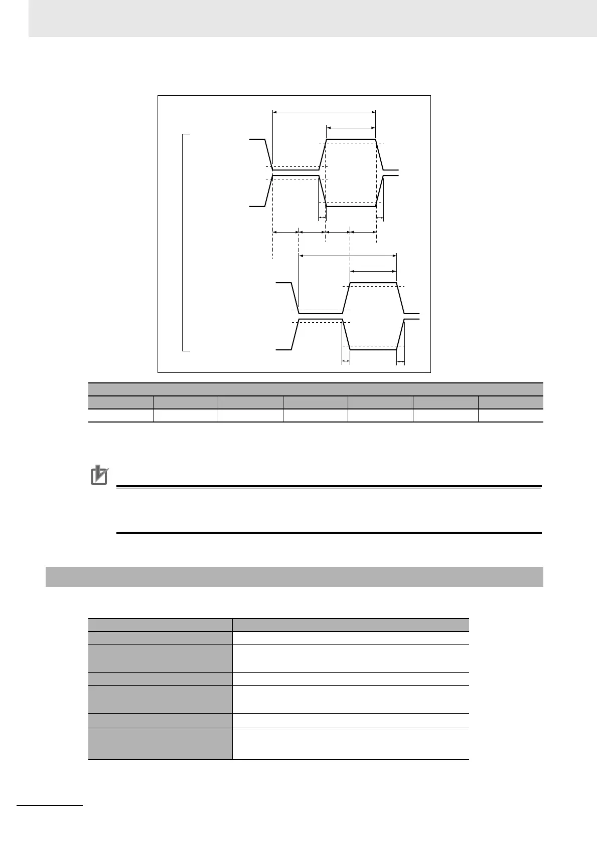
Timing conditions
A B C D E F G
< 25 ns > 125 ns > 250 ns > 0.5 μs> 1 μs > 0.25 μs > 0.5 μs
6-10-3 External Input Specifications
Item Specifications
Input voltage 20.4 to 28.8 VDC (24 VDC +20%/−15%)
Input current NX-EC0112 or NX-EC0122: 4.6 mA typical (24 VDC)
NX-EC0132 or NX-EC0142: 3.5 mA typical (24 VDC)
ON voltage/ON current 15 VDC min./3 mA min.
OFF voltage/OFF current NX-EC0112 or NX-EC0122: 4.0 VDC max./1 mA max.
NX-EC0132 or NX-EC0142: 5.0 VDC max./1 mA max.
ON response time
1
μs max.
OFF response time
NX-EC0112 or NX-EC0122: 2
μs max.
NX-EC0132 or NX-EC0142: 1
μs max.
F
F
F
F
E
D
A
A
ON
OFF
ON
OFF
A (+)
A (-)
E
D
A
A
ON
OFF
ON
OFF
B (+)
B (-)
Relationship between Phase A and Phase B on Phase Differential Pulse Inputs
Phase A
Phase B
ON
voltage
ON
voltage
OFF
voltage
OFF
voltage
Terminal inputs

 Loading...


