6 - 79
6 Incremental Encoder Input Units
NX-series Position Interface Units User’s Manual (W524)
6-10 Specifications
6
6-10-2 Pulse Input Specifications
Precautions for Correct Use
To satisfy the specifications for counter input, the type of output drive from the encoder that you
use, the encoder cable length, and the count pulse frequency must all be taken into consider-
ation.
The following table shows the pulse input specifications for the Units with line receiver inputs
(NX-EC0132 and NX-EC0142).
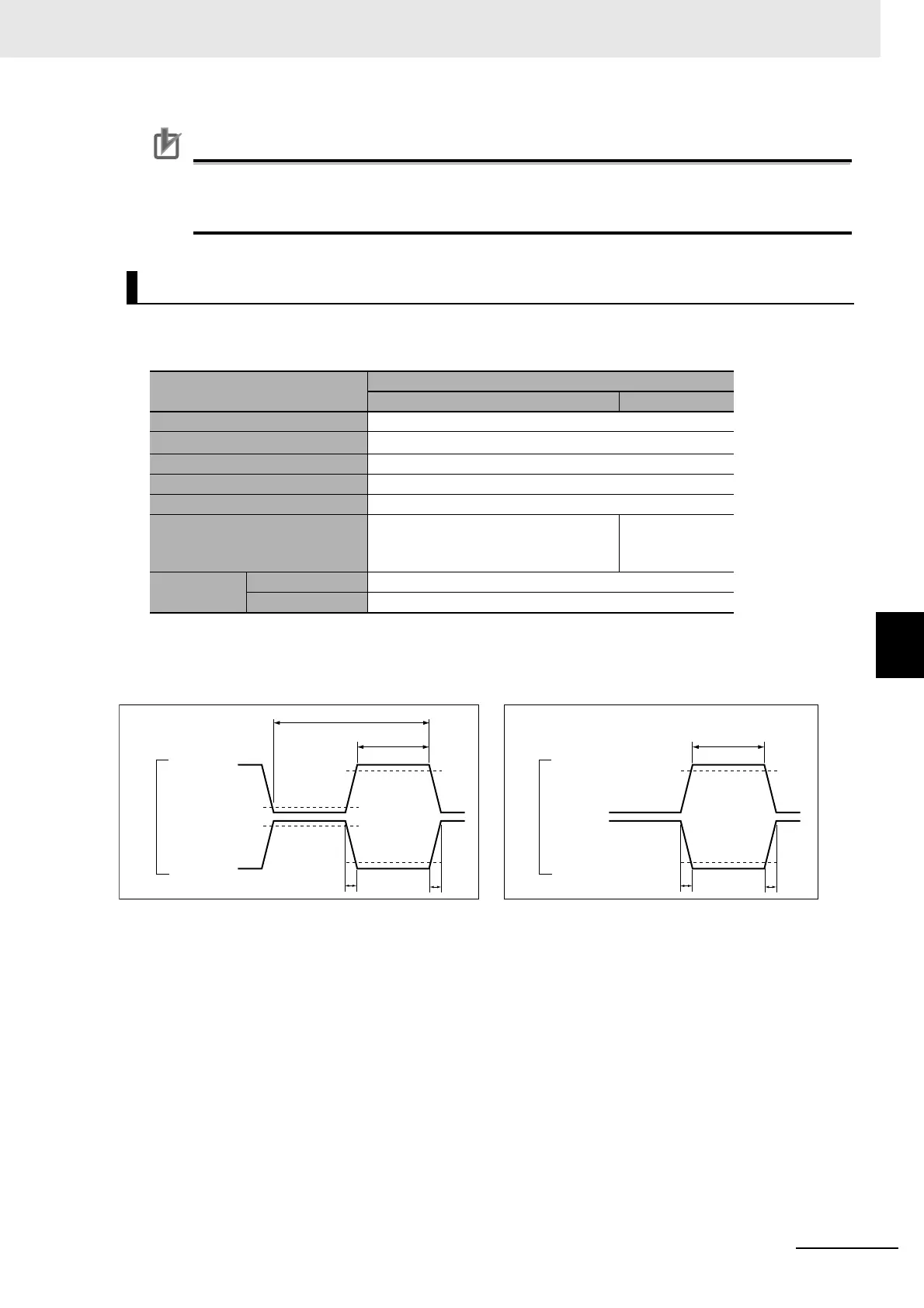
Pulse Input Timing Specifications
Line Receiver Input Specifications
Item
Specifications
Phases A and B Phase Z
Input voltage EIA standard RS-422-A line driver levels
Input impedance
120
Ω ±5%
High level input voltage VIT+ : 0.1 V min.
Low level input voltage VIT− : −0.1 V max.
Hysteresis voltage Vhys (VIT+ − VIT-): 60 mV
Maximum response frequency Single-phase 4 MHz (Phase differen-
tial pulse input, x4 multiplication: 1
MHz)
1 MHz
Encoder 5-V
power supply
Output voltage 5 VDC ±5%
Output current 500 mA max.
C
B
A
A
ON
OFF
ON
OFF
A/B (+)
A/B (-)
G
A
A
ON
OFF
ON
OFF
Z (+)
Z (-)
Counter Input (Phases A and B)
Input pulse duty = 50%
Counter Input Phase Z
ON
voltage
ON
voltage
OFF
voltage
OFF
voltage
Terminal input
Terminal input

 Loading...


