8 Pulse Output Units
8 - 14
NX-series Position Interface Units User’s Manual (W524)
8-6 Terminal Block Arrangement
The Pulse Output Unit uses screwless clamping terminal blocks.
This section describes the terminal block arrangements of the Unit.
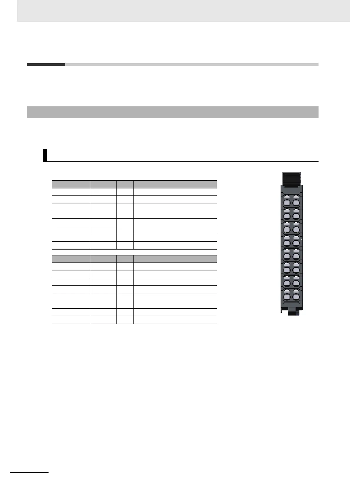
This section provides diagrams of the terminal block arrangement and internal power supply wiring of
the NX-PG0112. It also provides a wiring example.
A 16-terminal terminal block is used.
Note The sensor power supply output (24 V and 0 V) is provided power from the I/O power supply connected to
the Communications Coupler Unit or an Additional I/O Power Supply Unit.
8-6-1 NX-PG0112
Terminal Block Arrangement
Terminal No. Symbol I/O Name
A1 A O Pulse output A (CW/PLS)
A2 IOV O Pulse output, 24 V
A3 O0 O External output 0
A4 IOV O External output, 24 V
A5 NC --- Not used.
A6 I0 I External input 0
A7 IOV O Sensor power supply output, 24 V
A8 IOG O Sensor power supply output, 0 V
Terminal No. Symbol I/O Name
B1 B O Pulse output B (CW/DIR)
B2 IOV O Pulse output, 24 V
B3 NC --- Not used.
B4 IOV O External output, 24 V
B5 NC --- Not used.
B6 I1 I External input 1
B7 IOV O Sensor power supply output, 24 V
B8 IOG O Sensor power supply output, 0 V
A
IOV
O0
IOV
NC
I0
IOV
IOG
B
IOV
NC
IOV
NC
I1
IOV
IOG
A B
A
B
1 1
2 2
3 3
4 4
5 5
6 6
7 7
8 8

 Loading...


