6 - 41
6 Incremental Encoder Input Units
NX-series Position Interface Units User’s Manual (W524)
6-7 I/O Data Specifications
6
6-7-2 Data Details
Precautions for Correct Use
The Encoder Counter Operation Command parameter is normally used by assigning it as I/O
data. However, do not assign this parameter as I/O data when you assign it to an MC Function
Module axis.
When you assign the parameter to an MC Function Module axis, manipulate the parameter
through the MC Function Module axis and not in the parameter itself.
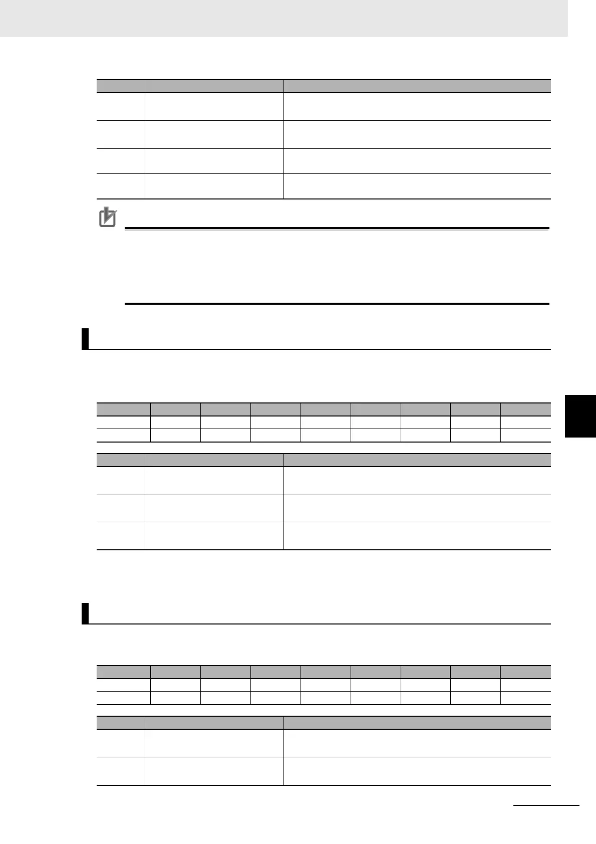
The bit configuration of the Pulse Period Measurement Function parameter is given in the following
table.
n: Channel number
The bit configuration for the Latch Function parameter is given in the following table.
n: Channel number
ERENn External Reset Enable 1: Reset for external reset enabled.
0: Reset for external reset disabled.
ZSENn Phase Z Reset Enable 1: Reset for phase-Z signal enabled.
0: Reset for phase-Z signal disabled.
ERCRn External Reset Completed Flag
Clear
0 to 1: External Reset Completed Flag cleared.
ZSCRn Phase Z Reset Completed Flag
Clear
0 to 1: Phase Z Reset Completed Flag cleared.
Pulse Period Measurement Function
Byte Bit 7 Bit 6 Bit 5 Bit 4 Bit 3 Bit 2 Bit 1 Bit 0
0 --- --- --- --- --- PPOFRn PPVCRn PPENn
1 --- --- --- --- --- --- --- ---
Abbr. Data Description
PPENn Pulse Period Measurement
Enable
*1
*1. If the Edge Detection Method parameter is set to 0, the function is disabled regardless of the status of this bit.
1: Pulse period measurement enabled.
0: Pulse period measurement disabled.
PPVCRn Pulse Period Measurement
Value Clear
*2
*2. This can be performed only when pulse period measurement is enabled.
0 to 1: Pulse period measured value and pulse period measure-
ment counter are cleared.
PPOFRn Pulse Period Measurement
Value Overflow Flag Clear
*2
0 to 1: Pulse period measurement value overflow flag is cleared.
Latch Function
Byte Bit 7 Bit 6 Bit 5 Bit 4 Bit 3 Bit 2 Bit 1 Bit 0
0 --- --- --- --- --- LSEL1n LTRG1n LEN1n
+1 --- --- --- --- --- LSEL2n LTRG2n LEN2n
Abbr. Data Description
LEN1n Latch Input 1 Enable 1: Enable the latch input 1.
0: Disable the latch input 1.
LTRG1n
Latch Input 1 Trigger Condition
*1
0: One-shot Mode
1: Continuous Mode
Abbr. Data Description

 Loading...


