8 - 19
8 Pulse Output Units
NX-series Position Interface Units User’s Manual (W524)
8-6 Terminal Block Arrangement
8
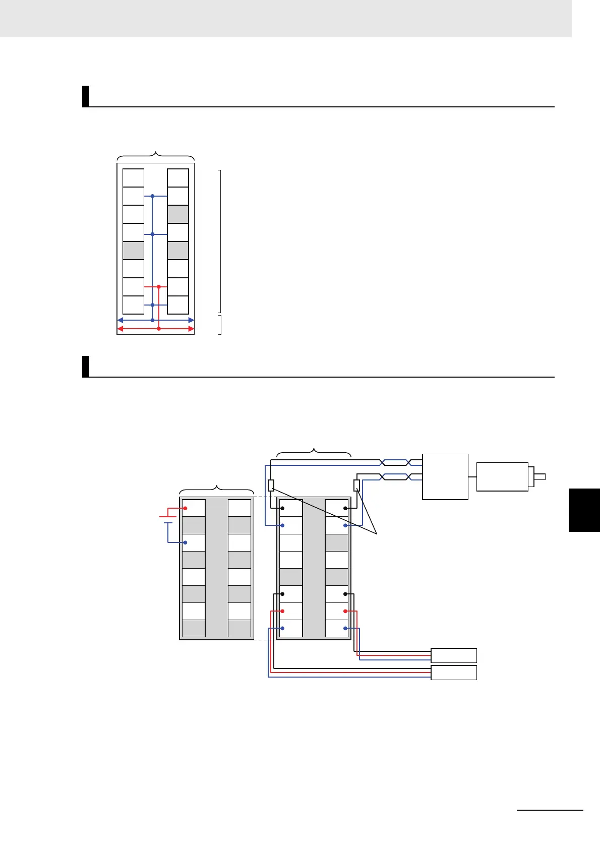
8-6-2 NX-PG0122
The following diagram shows the internal power supply wiring.
This section provides examples of how to wire the Unit to stepper motor drives and servo drives.
Wiring Example for Stepper Motor Drives
Note 1. The pulse output, external output, and external inputs are all PNP connections.
2. To supply power to connected external devices, connect an 24-VDC I/O power supply to the Communi-
cations Coupler Unit or an Additional I/O Power Supply Unit to supply power to the Pulse Output Unit.
Internal Power Supply Wiring Diagram
Wiring Example
A
IOG
O0
IOG
NC
I0
IOG
B
IOG
NC
IOG
NC
I1
IOG
IOV IOV
24 V
0 V
Terminal block
NX bus connector
Pulse Output Unit
Note The I/O power is supplied from the I/O power supply connected
to the I/O power supply terminals on the Communications Cou-
pler Unit or an Additional I/O Power Supply Unit.
Stepper
motor
Sensor 1
Sensor 2
A
IOG
O0
IOG
NC
I0
IOG
B
IOG
NC
IOG
NC
I1
IOG
IOV
IOG
IOV
IOG
IOV
IOG
IOV
IOG
IOV IOV
Drive
Pulse: 2
Current-limiting resistor
Pulse Output Unit
I/O power
supply (24 VDC)
Additional I/O
Power Supply Unit

 Loading...


