8 - 37
8 Pulse Output Units
NX-series Position Interface Units User’s Manual (W524)
8-8 I/O Data Specifications
8
8-8-2 Data Details
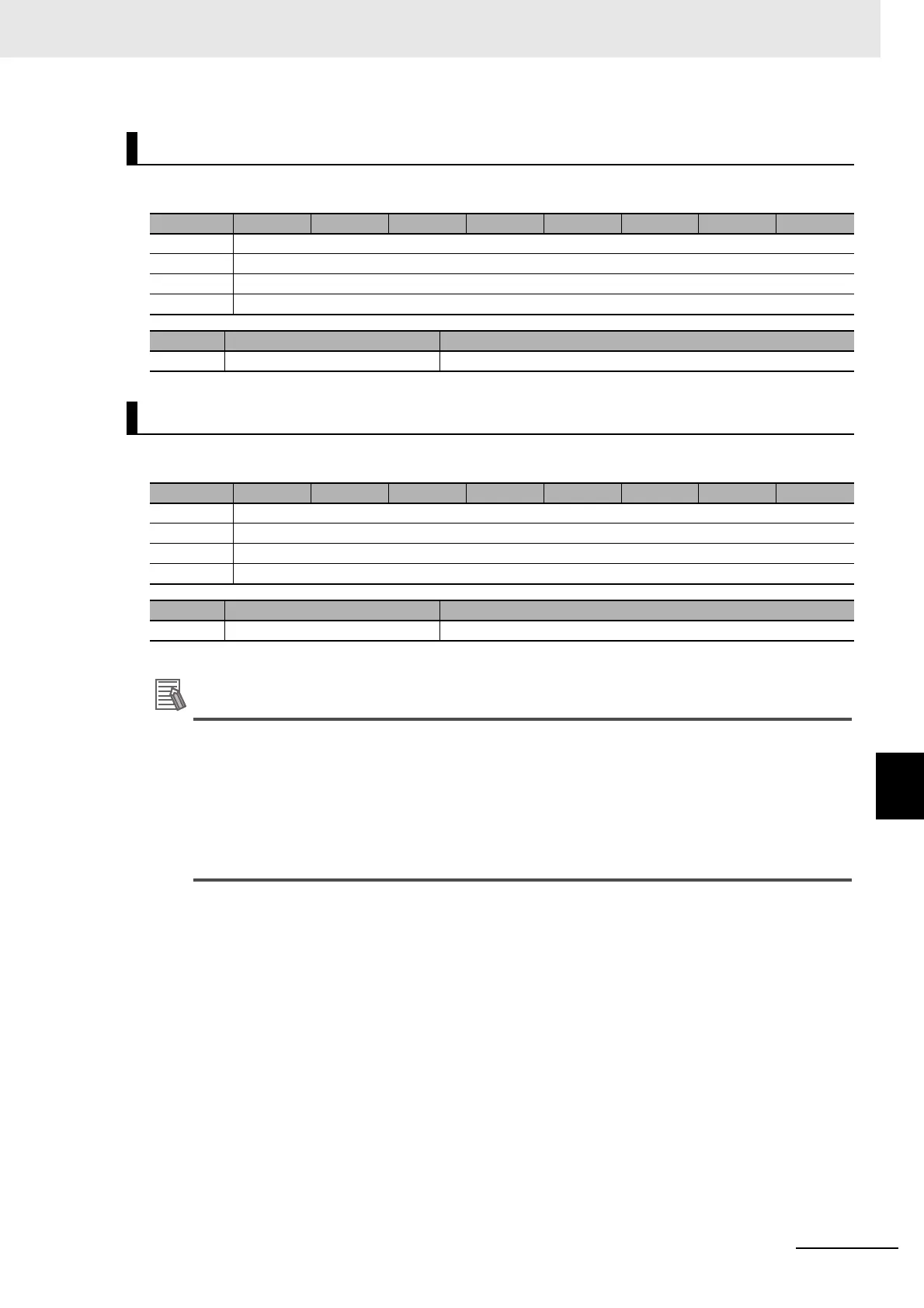
The bit configuration of the Command Position variable is given in the following table.
The bit configuration of the Command Velocity variable is given in the following table.
The command velocity is only used when the Output Mode Selection parameter is set to a
velocity-continuous pulse output.
For position-synchronous pulse output, the set value for the Command Velocity parameter is
ignored.
The command velocity for velocity-continuous pulse output is signed 32-bit (DINT) data. How-
ever, the set value itself is handled as an absolute value, regardless of the sign. The pulse out-
put direction is determined by the sign of the command position.
Command Position
Byte Bit 7 Bit 6 Bit 5 Bit 4 Bit 3 Bit 2 Bit 1 Bit 0
0 POP (Command Position LL)
+1 POP (Command Position LH)
+2 POP (Command Position HL)
+3 POP (Command Position HH)
Abbr. Data Description
POP Command Position This contains the command position.
Command Velocity
Byte Bit 7 Bit 6 Bit 5 Bit 4 Bit 3 Bit 2 Bit 1 Bit 0
0 POV (Command Velocity LL)
+1 POV (Command Velocity LH)
+2 POV (Command Velocity HL)
+3 POV (Command Velocity HH)
Abbr. Data Description
POV Command Velocity This contains the command velocity.

 Loading...


