Appendices
A - 18
NX-series Position Interface Units User’s Manual (W524)
NX-ECS112
Unit name SSI Input Units Model NX-ECS112
Number of channels
1 channel
Type of external con-
nections
Screwless clamping terminal block
(12 terminals)
I/O refreshing
method
*1
Free-Run refreshing, synchronous I/O refreshing, or task period prioritized refreshing
Indicators
Refer to NX-ECS112 on page
7-9.
I/O signals
SSI inputs: 2, Data input (D+, D-)
SSI outputs: 2, Clock output (C+, C-)
I/O interface Synchronized serial interface (SSI)
Clock output EIA standard RS-422-A line driver levels
Data input EIA standard RS-422-A line receiver levels
Maximum data length 32 bits (The single-turn, multi-turn, and status data length can be set.)
Coding method No conversion, binary code, or gray code
Baud Rate 100 kHz, 200 kHz, 300 kHz, 400 kHz, 500 kHz, 1.0 MHz, 1.5 MHz, or 2.0 MHz
Dimensions 12 × 100 × 71 mm (W×H×D) Isolation method Digital isolator
Insulation resistance
20 MΩ min. between isolated cir-
cuits (at 100 VDC) Dielectric strength
510 VAC between isolated circuits
for 1 minute with leakage current of
5 mA max.
I/O power supply
method
Supplied from the NX bus.
20.4 to 28.8 VDC (24 VDC
+20%, −15%)
Current capacity of
I/O power supply ter-
minals
IOV: 0.3 A max. per terminal
IOG: 0.3 A max. per terminal
NX Unit power con-
sumption
0.85 W max.
Current consump-
tion from I/O power
supply
20 mA max.
Maximum transmis-
sion distance
*2
Baud Rate Maximum transmission distance
100 kHz 400 m
200 kHz 190 m
300 kHz 120 m
400 kHz 80 m
500 kHz 60 m
1.0 MHz 25 m
1.5 MHz 10 m
2.0 MHz 5 m
Weight 65 g max.
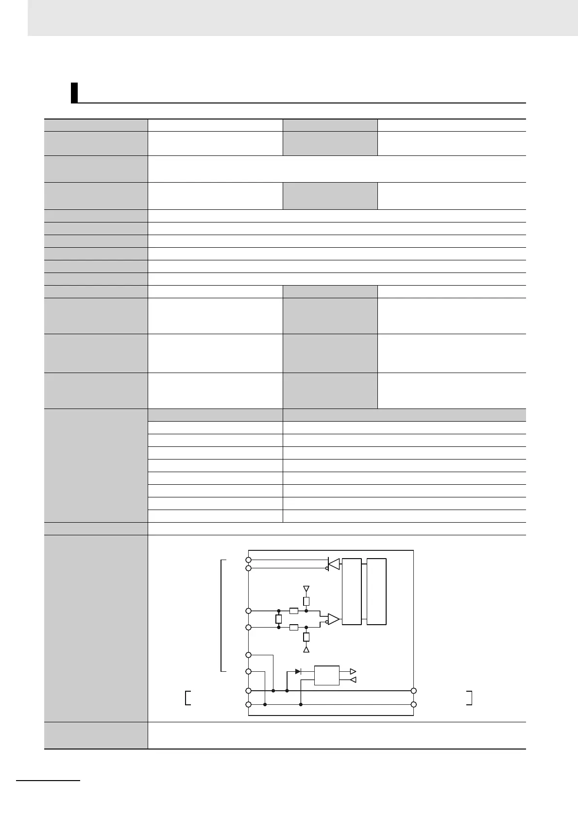
Circuit layout
SSI Clock Output and Data Input
Installation orientation
and restrictions
Installation orientation: 6 possible orientations
Restrictions: There are no restrictions.
120
Ω
No isolation: 5 V GND
No isolation: 5 V
No isolation: 5 V GND
Terminal block
No isolation: 5 V
I/O power supply +
I/O power supply
−
I/O power supply +
I/O power supply
−
Left-side
NX bus
connector
Right-side
NX bus
connector
D+
D-
C+
C-
IOV
IOG
Isola-
tion
cir-
cuit
Inter-
nal
cir-
cuits
Non-
isolated
power
supply

 Loading...


