A - 27
Appendices
NX-series Position Interface Units User’s Manual (W524)
A-1 Datasheets
A
A-1-4 Pulse Output Units
Insulation resistance
20 MΩ min. between isolated cir-
cuits (at 100 VDC) Dielectric strength
510 VAC between isolated circuits
for 1 minute with leakage current of
5 mA max.
I/O power supply
method
Supplied from the NX bus.
20.4 to 28.8 VDC (24 VDC
+20%, −15%)
Current capacity of
I/O power supply ter-
minals
IOV: 0.1 A max. per terminal
IOG: 0.1 A max. per terminal
NX Unit power con-
sumption
0.90 W max.
Current consump-
tion from I/O power
supply
20 mA max.
Weight 70 g max. Cable length 3 m max.
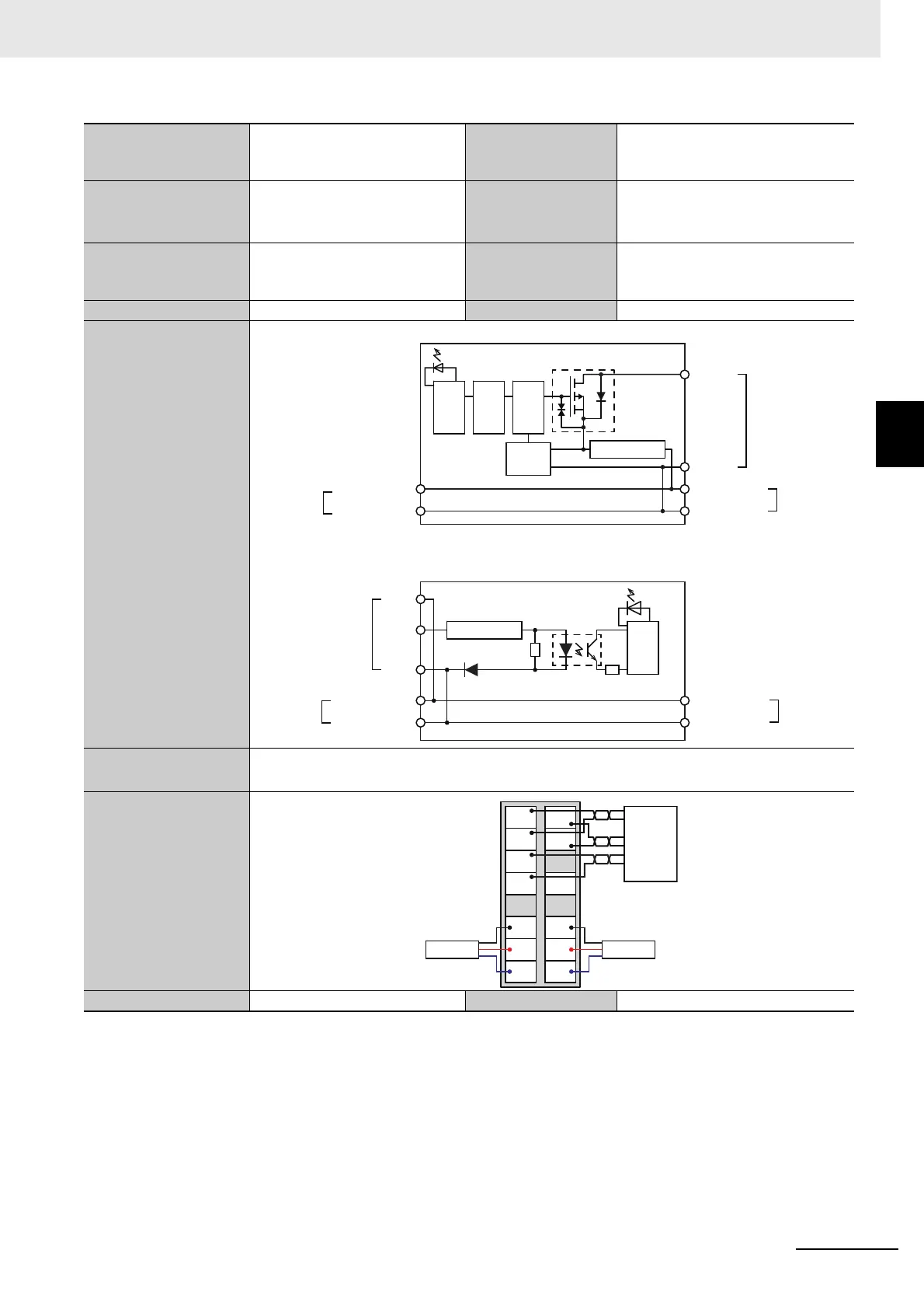
Circuit layout
Pulse Output and External Output
External Inputs
Installation orientation
and restrictions
Installation orientation: 6 possible orientations
Restrictions: There are no restrictions.
Terminal connection
diagram
Failure detection None Protection None
*1. The I/O refreshing method is automatically set according to the connected Communications Coupler Unit and CPU Unit.
*2. These functions are supported when you also use the MC Function Module in the NJ/NX-series CPU Unit.
Refer to the NJ/NX-series CPU Unit Motion Control User’s Manual (Cat. No. W507) for details.
A Pulse Output Unit only outputs pulses during the control period based on commands received at a fixed period.
Target position calculations (distribution calculations) for acceleration/deceleration control or for each control period must
be performed on the Controller that is connected as the host.
Inter-
nal
cir-
cuits
A, B, O0
IOG
Terminal block
I/O power supply +
I/O power supply
−
I/O power supply +
I/O power supply
−
Left-side
NX bus
connector
Right-side
NX bus
connector
Non-
isolated
power
supply
Isola-
tion
cir-
cuit
Drive
circuit
Short-circuit protection
I0 or I1
Inter-
nal
cir-
cuits
IOG
IOV
Terminal block
Current limiter
I/O power supply +
I/O power supply
−
I/O power supply +
I/O power supply
−
Left-side
NX bus
connector
Right-side
NX bus
connector
A
IOG
O0
IOG
B
IOG
NC
IOG
NC
I0
IOV
IOG
NC
I1
IOV
IOG
Driver
Sensor 1 Sensor 2

 Loading...


