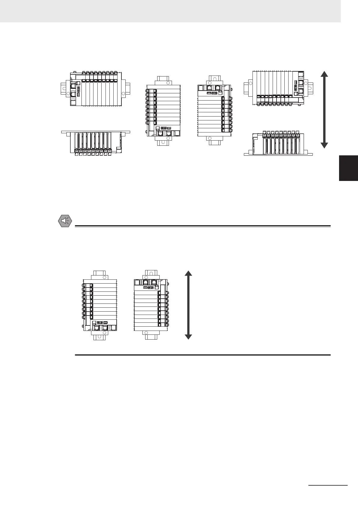
(A) is the upright installation orientation and (B) to (F) are installation orientations other than upright.
(A)
(B)
(E)
Upper
Lower
(C)
(F)
(D)
However, there are restrictions on the installation orientation and restrictions to the specifications that
can result from the Communications Coupler Units and NX Units that are used.
For detailed restrictions, refer to the user’
s manuals for the Communications Coupler Units, NX Units,
and NX-series System Units that you will use.
Precautions for Safe Use
• For the installation orientations in the following figure, support the cables, e.g., with a duct, so
that the End Plate on the bottom is not subjected to the weight of the cables. The weight of
the cables may cause the bottom End Plate to slide downward so that the Slave Terminal is
no longer secured to the DIN T
rack, which may result in malfunctions.
3 Installation and Wiring
3 - 7
NX-series Safety Control Unit User's Manual (Z930)
3-1 Installing Units
3
3-1-4 Installation Orientation

 Loading...


