8 Checking Operation and Actual Operation
8 - 22
NX-series Safety Control Unit User’s Manual (Z930)
When Sysmac Studio Is Connected to Communications Coupler Unit
1 Place the Sysmac Studio online with the Communications Coupler Unit.
Place the Sysmac Studio online with the Communications Coupler Unit that the Safety CPU Unit
is connected to. The following procedure cannot be executed on a Communications Coupler
Unit that the Safety CPU Unit is not connected to.
2 Place the Safety CPU Unit in DEBUG mode.
Refer to 8-4 Changing to DEBUG Mode on page 8-17 for a detailed procedure.
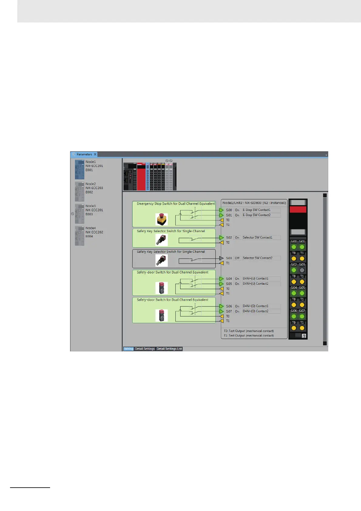
3 Double-click Parameters under the name of the Safety I/O Unit under Configurations and
Setup − Communications − Safety − Safety I/O.
The Parameters Tab Page shown below is displayed. Select the Safety I/O Unit to monitor.

 Loading...


