Application Overview
Safety category/PL Safety device Stop category Reset
Equivalent to 2/PLc
(Single Beam Safety Sen-
sor)
• Emergency stop pushbutton
• Single beam safety sensor
0 Manual
Motor M stops when emergency stop pushbutton S1 is pressed.
Motor M stops when the light in the single beam safety sensor is interrupted.
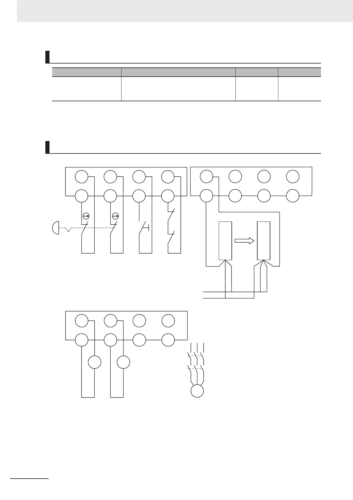
Wiring
Si0 Si1
T0 T1
Si2 Si3
T0 T1
KM1
KM2
S2
Si0 Si1 Si2 Si3
T0 T1 T0 T1
24 VDC
GND
Emitter
Receiver
S3
24 V (brown)
0 V (blue)
Test input (pink)
Control output (black)
Mode (pink)
24 V (brown)
0 V (blue)
Unit 2 (NX-SIH400)
Unit4 (NX-SOD400)
Unit 3 (NX-SIH400)
KM1 KM2
M
KM1
KM2
So0 So1 So2 So3
IOG
S1: Emergency stop pushbutton
S2: Reset switch
S3: Single beam safe
ty sensor
KM1, KM2: Contactors
M: Motor
IOG IOG IOG
S1
Appendices
A - 64
NX-series Safety Control Unit User's Manual (Z930)

 Loading...


