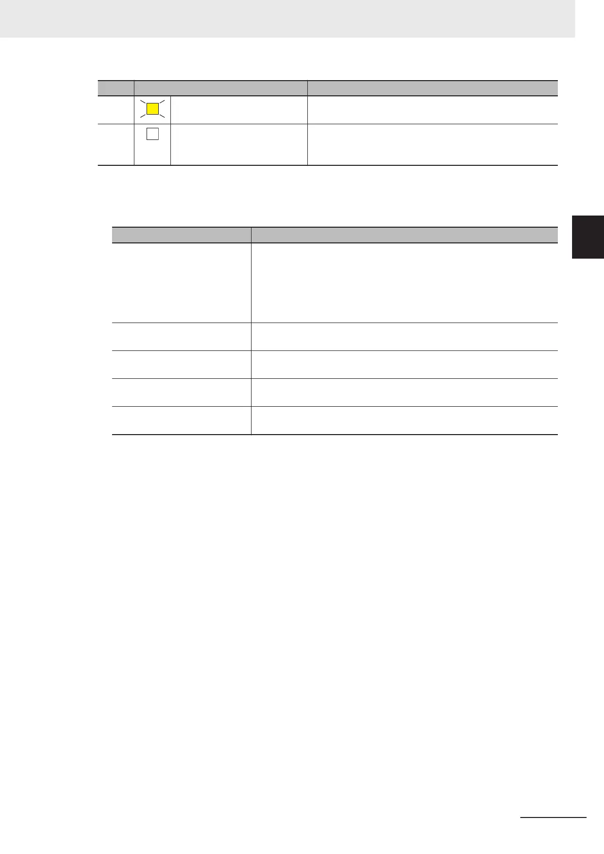
Color Status Meaning
Yellow Lit Safety application data from the execution of the safety vali-
dation is stored in the non-volatile memory.
---
Not lit Safety application data from the execution of the safety vali-
dation is not stored in the non-volatile memory, or a fatal
fault has occurred.
l
Seven-segment Indicator
The two-digit seven-segment indicator shows the detailed information on the Safety CPU Unit.
Item Meaning
At normal operation It shows the lowest one byte of the safety signature for the safety pro-
gram that is operating. If the safety signature is not confirmed, “—“ is dis-
played.
While a CIP Safety originator connection is being established, the indica-
tor flashes. When all the CIP Safety originator connections are establish-
ed, the indicator is lit.
When an error occurs Refer to 12-2-1 Troubleshooting the Main Errors in the Safety CPU Unit
on page
12 - 3.
When a signature code is
checked
Refer to A-14 Checking the Signature Code on the Seven-segment Indi-
cator on page A -
101.
When the Safety Unit Restore is
executed
Refer to 10-1-2 Safety Unit Restore Function on page 10 -
3.
When the Safety Data Logging
is executed
Refer to 11-4 Checking the Logging Status
on page 11 - 7.
2 Specifications
2 - 15
NX-series Safety Control Unit User's Manual (Z930)
2-1 Safety CPU Unit
2
2-1-3 Indicators

 Loading...


