6 System Configuration and Setup
6 - 12
NX-series Safety Control Unit User’s Manual (Z930)
6-5 Setting the Safety Input and Output
Functions
You set the safety input functions and safety output functions of the Safety I/O Unit when you assign
input devices and output devices to the Safety I/O Unit with the Sysmac Studio.
This section describes how to assign devices that are connected. Refer to 3-3-1 Safety Input Functions
on page 3-11 and 3-3-2 Safety Output Functions on page 3-35 for details on the safety input functions
and safety output functions.
1 In the Multiview Explorer, select the Safety CPU Unit in the Controller Selection Box.
2 Double-click Parameters under the name of the Safety I/O Unit under Configurations and
Setup − Communications − Safety − Safety I/O.
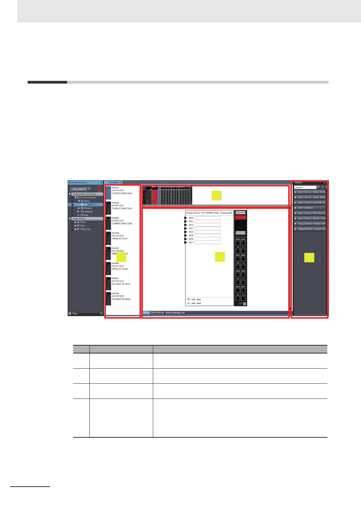
The Parameters Tab Page shown below is displayed.
The items in the Safety Slave Unit Parameter Settings Tab Page are described below.
Item Name Function
(a) Coupler Unit List Pane This pane lists the Coupler Units that can perform safety communica-
tions with the Safety CPU Unit.
(b) Slave Terminal Configu-
ration Pane
This pane displays the slave terminal configuration of the Communica-
tions Coupler Unit that is selected in the Coupler Unit List Pane.
(c) Toolbox The toolbox displays the input and output devices that can be set for
the Safety I/O Units.
(d) Parameter Settings
Pane
This pane is used to make settings for the input and output devices
that are set for the Safety I/O Units. You can arrange the devices, set
diagnosis functions, change icons, etc.
Refer to A-7 Icon list for Safety Slave Unit Parameters on page A-69
for details.