EasyManua.ls Logo

Omron NX-SID800 User Manual

Omron NX-SID800
492 pages
To Next Page IconTo Next Page
To Previous Page IconTo Previous Page
Page #220 background imageLoading...
Page #220 background image
7 Programming
7 - 20
NX-series Safety Control Unit Users Manual (Z930)
7-3 Constants (Literals)
This section describes constants.
The value of a variable changes depending on the data that is assigned to that variable. The value of a
constant never changes.
Unlike variables, constants are not stored in memory. You can use constants in the algorithm of a POU
without the need to declare them.
Constants have a data type in the same way as variables.
The following types of constants can be used with Safety Control Units.
•Bits
Numbers
Bit strings
•Times
The following tables show the notation to define different constants for the Safety Control Unit. The con-
stant is normalized after it is entered.
Integers
7-3-1 Constants
7-3-2 Types of Constants
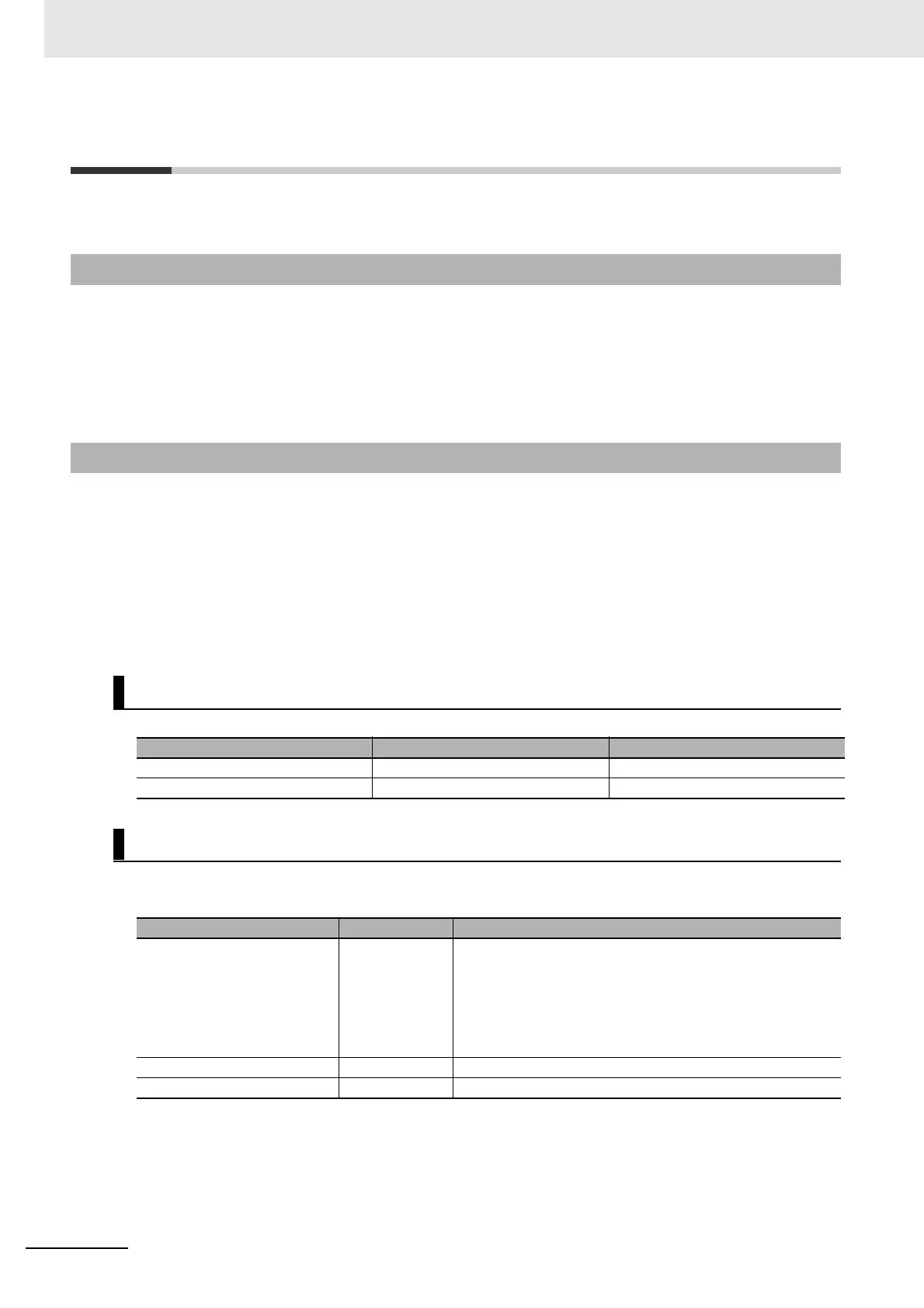
Bits
Notation Example Remarks
TRUE or FALSE FALSE or TRUE
{data_type}#{numeric_value] bool#0 or bool#1 Data type: BOOL
Numbers
Notation Example Remarks
{data_type}#{base}#{numeric_
value]
int#10#1 Data type: int or dint
Base: 2, 8, 10, or 16
The editor on the Sysmac Studio does not show the base
of 10. Values entered as the base of 8 are converted to
decimal numbers.
Numeric values cannot be signed (+ or ).
{data_type}#{numeric_value] int#1 This is interpreted as decimal data.
{numeric_value} 100 This is interpreted as SAFEINT or SAFEDINT data.

Table of Contents

Other manuals for Omron NX-SID800

Question and Answer IconNeed help?

Do you have a question about the Omron NX-SID800 and is the answer not in the manual?

Omron NX-SID800 Specifications

General IconGeneral
ModelNX-SID800
Input Voltage24 VDC
Number of Input Points8
Number of Output Points0
Number of I/O Points8
Safety StandardIEC 61508 SIL3, ISO 13849-1 PLe
Connection MethodRemovable terminal block
Safety Category4

Summary

Introduction

Safety Precautions

Warnings

Setting Up a Risk Assessment System

Emphasizes early risk assessment in design to identify dangers and optimize product selection.

Design

Debugging

Testing Operation

Wiring

Replacing Units

Precautions for Safe Use

Precautions for Correct Use

Actual Operation

Ensures correct unit connection, safety signature verification, and confirms destination before data transfer.

Periodic Inspections and Maintenance

Regulations and Standards

Conformance to EN ISO 13849-1 and EN 62061

Overview

1-1 Introduction and Features

Introduces the NX-series Safety Control Units, their features, system configuration, and application procedures.

1-2 System Configuration and Configuration Devices

Explains system configuration for safety controls on EtherCAT and EtherNet/IP networks.

1-5 Commissioning Procedures

Outlines the step-by-step procedure to build a safety system, divided into standard and safety control stages.

2-1 General Specifications

2-2 Specifications of Individual Units

2-2-1 Models

Lists the available models for Safety CPU Units, Safety Input Units, and Safety Output Units.

2-2-2 Safety CPU Unit

2-2-3 Safety Input Units

2-2-4 Safety Output Units

2-3 PFH Values

2-3-1 Safety CPU Unit

Lists the PFH values for NX-SL3300 and NX-SL3500 Safety CPU Units.

2-3-2 Safety Input Units

Lists the PFH values for NX-SID800 and NX-SIH400 Safety Input Units.

2-3-3 Safety Output Units

Lists the PFH values for NX-SOD400 and NX-SOH200 Safety Output Units.

Part Names and Functions

3-1 Safety CPU Unit

Details the parts and names of the Safety CPU Unit, including marker attachment locations and indicators.

3-1-1 Parts and Names

Identifies the parts of the NX-SL3300 or NX-SL3500 Safety CPU Unit and their functions.

3-2 Safety I/O Units

Details the parts and names of Safety I/O Units, including terminal blocks and indicators.

3-2-1 Parts and Names

Identifies the parts of NX-SIH400, NX-SID800, NX-SOD400, and NX-SOH200 Safety I/O Units.

3-3 Safety I/O Functions

Explains various safety I/O functions, including connectable input devices and self-diagnosis features.

3-3-1 Safety Input Functions

Details safety input functions, including connectable input devices, their types, and parameters.

3-3-2 Safety Output Functions

Explains safety output functions, including connectable output devices and connection methods for I/O power supply.

Calculating Safety Reaction Times

4-1 Safety Reaction Times

Describes how to calculate safety reaction times for Safety Control Units, including response times of components.

4-1-1 Safety Reaction Times

Defines safety reaction time as the time to turn OFF an output considering failures and breakdowns.

4-1-2 Calculating Safety Reaction Times

Explains the calculation of safety reaction time by summing sensor/switch response, I/O refresh, and actuator response times.

4-1-3 Verifying Safety Reaction Times

Describes the process of verifying calculated safety reaction times against required specifications.

4-2 Safety Task

Describes the safety task of the Safety CPU Unit and its effect on safety reaction times.

4-2-1 Safety Task

Explains the purpose of the safety task in assigning execution conditions for processes like data exchange and program execution.

4-2-2 Operation of Safety Task

Details the repetitive operations performed for the safety task, including input data processing and program execution.

4-2-3 Calculating the Minimum Safety Task Period

Provides methods to find the minimum safety task period based on EtherCAT and EtherNet/IP network configurations.

4-2-4 Setting the Safety Task Period

Describes how to approximate the safety task period using formulas involving minimum safety task period and expansion communications monitoring time.

4-3 FSoE Watchdog Timers

Explains FSoE watchdog timers used for timeouts in safety process data between Safety CPU Unit and Safety I/O Unit.

4-3-1 FSoE Watchdog Timers

Defines FSoE watchdog timers as used for timeouts in safety process data between Safety CPU Unit and Safety I/O Unit.

4-3-2 Checking FSoE Watchdog Timers

Provides procedures to check FSoE watchdog timer values within Sysmac Studio.

4-3-3 Settings for FSoE Watchdog Timers

Explains how to find set values for FSoE watchdog timers based on safety task periods.

4-3-4 Changing FSoE Watchdog Timers

Details procedures for changing FSoE watchdog timer values using Sysmac Studio.

Installation and Wiring

5-3-2 Checking Wiring

System Configuration and Setup

6-1 Configuration and Setup Procedures

Outlines the procedures for using Sysmac Studio to configure and set up the safety control system.

6-3 Controller Configuration and Setup of the Safety Control Units

Describes configuration and setup procedures for Safety Control Units on EtherCAT and EtherNet/IP Slave Terminals.

6-3-1 Procedures for Creating the Controller Configuration for Safety Control

Provides step-by-step instructions for creating controller configurations for Safety Control Units on EtherCAT Slave Terminals using Sysmac Studio.

6-3-2 Setting and Viewing the Safety Control Unit Settings

Describes how to set and view settings for Safety CPU Units and Safety I/O Units, including device names and model numbers.

6-4 Setting Up the Safety Process Data Communications

Explains how to view or change safety process data communications settings automatically set when adding a Safety Control Unit.

6-5 Setting the Safety Input and Output Functions

Describes how to set safety input and output functions of Safety I/O Units by assigning input and output devices in Sysmac Studio.

6-6 Registering Device Variables

Details how to register device variables for I/O ports to access external devices from safety programs.

Programming

7-1 POUs (Program Organization Units)

Explains POUs (Programs, Function Blocks, Functions) as building blocks for safety programs.

7-1-1 What Are POUs?

Defines POU as a unit in the IEC 61131-3 model, including local variables and algorithms.

7-1-2 Overview of the Three Types of POUs

Provides an overview of Programs, Function Blocks (FBs), and Functions (FUNs) as types of POUs.

7-1-3 Differences between Programs, Functions, and Function Blocks

Compares Programs, Function Blocks, and Functions in terms of type, execution method, and algorithm.

7-1-4 Details on Programs

Describes program structure, including local variable tables, algorithms, and execution order.

7-1-5 Details on Function Blocks

Explains function block definitions, instances, parameters, and procedures for creating them.

7-1-6 Details on Functions

Describes functions, their structures, instruction names, and the inability to create user-defined functions.

7-1-7 Instructions

Defines instructions as the smallest processing elements, including FB and FUN instructions.

7-2 Variables

Describes variable designations in detail, including types, attributes, and data types used for I/O exchange and calculations.

7-7 Offline Debugging

Allows debugging programs without being connected online to a Safety CPU Unit using a Simulator.

7-7-1 Offline Safety Program Debugging

Best practice to simulate safety programs on the computer to check operation logic and parameter settings.

Checking Operation and Actual Operation

8-1 Procedures before Operation and Transferring the Required Data

Covers procedures before operating the Safety CPU Unit, including commissioning and data transfer.

8-1-1 Commissioning Procedure

Details the step-by-step procedure to start operating the Safety CPU Unit after writing safety programs.

8-2 Transferring the Configuration Information

Describes how to start communications and transfer configuration information from Sysmac Studio to the controller units.

8-2-1 Overview

Explains the necessity of transferring Slave Terminal settings before going online with the Safety CPU Unit.

8-3 Operating Modes of the Safety CPU Unit

Describes the operating modes of the Safety CPU Unit, state changes, and executable functions in each mode.

8-3-1 Startup Operating Mode and Changing the Operating Mode

Explains how the Safety CPU Unit changes to PROGRAM or RUN mode after power ON based on program validation.

8-4 Changing to DEBUG Mode

Describes how to place the Safety CPU Unit into DEBUG mode and transfer safety application data.

8-6 Functions for Checking Operation

Describes functions in Sysmac Studio used to check the operation on the Safety CPU Unit, allowing control and debugging.

8-6-1 Overview of Functions for Checking Operation

Lists functions for checking operation, including monitoring variables, controlling BOOL variables, and troubleshooting.

8-6-5 Controlling BOOL Variables, Changing Present Values, and Using Forced Refreshing

Explains debugging safety programs by controlling BOOL variables, changing present values, and using forced refreshing.

8-9 Performing Safety Validation and Operation

Describes the procedure for safety validation testing to confirm functions meet system specifications.

8-9-1 Performing Safety Validation

Details the process of performing safety validation after debugging programs, saving data to non-volatile memory.

8-9-2 Changing to RUN Mode

Explains procedures to change the Safety CPU Unit to RUN mode after performing safety validation.

8-9-3 Changing to PROGRAM Mode

Describes the procedure to change the Safety CPU Unit from RUN mode to PROGRAM mode.

Troubleshooting

9-1 Checking for Errors

Describes methods to check for errors in Safety Control Units, including checking indicators and using Sysmac Studio.

9-2 Checking for Errors with the Indicators

Explains how to use TS and FS indicators to check NX Unit status and errors, and provides troubleshooting procedures.

9-3 Checking for Errors with the Sysmac Studio

Describes using Sysmac Studio to check error meanings and troubleshooting procedures based on error management methods.

9-3-1 Checking for Errors from the Sysmac Studio

Explains how to check current Controller errors and logs of past Controller errors using Sysmac Studio's Controller Error Tab Page.

9-3-2 Types of Errors

Describes errors that can originate in the Safety CPU Unit and Safety I/O Units and how to correct them.

9-3-3 Event Codes for Errors and Troubleshooting Procedures

Lists errors (events) that can originate in the Safety CPU Unit and Safety I/O Units, including event codes and assumed causes.

9-3-4 Error Descriptions

Describes the information given for individual errors, including name, meaning, source, error attributes, effects, and cause/correction.

Maintenance and Inspection

Appendix

Related product manuals