8 - 11
8
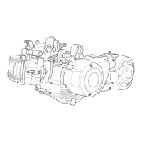
- Check the diameter of both the driving shaft supports
according to the axis and planes shown in the figure.
The half shafts are subdivided in Class 1 and Class 2,
as shown in the table below.
Standard
diameter
Class 1
Class 2
40.010 - 40.016
40.016 - 40.022
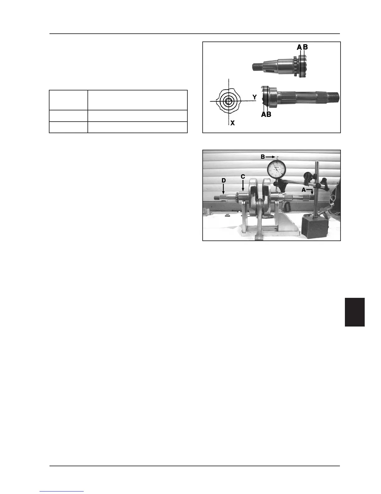
Driving shaft alignment check
- Assemble the driving shaft on the support. Measure
the disalignment in the 4 points shown in the figure.
Specific tool:
Support for driving shaft control 020074Y
05_270_2
05_270_1
Driving shaft crankcase
Max. out-of-line allowed: A = 0.15 mm
B = 0.01 mm
C = 0.01 mm
D = 0.10 mm
- Check the condition of the driving shaft cone, tange
seat, oil seal housing, and the threading.
- If necessary, replace the driving shaft.
N.B.: The main bearings cannot be ground.
The connecting rod cannot be replaced. To check the
connecting rod small end, see Chapter 7-Thermal Unit
and Timing System.
- While cleannig the driving shaft, make sure that no
dirt enters the shaft lubrication hole.
 Loading...