Fuel injection
9 - 36
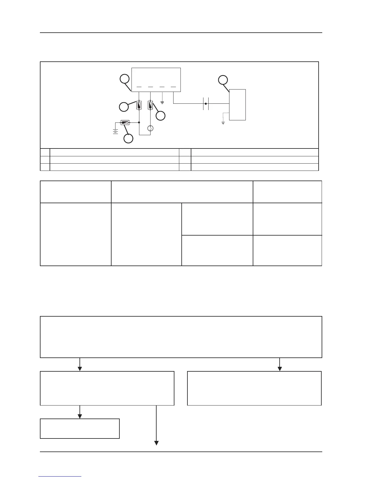
FUEL INJECTION INDICATOR CIRCUIT
CIRCUIT DIAGRAM
TERMINAL CONDITIONS STANDARD VALUES
15 - 23
- commutator set to
"ON"
- side stand raised
- switch set to "RUN"
during checks
after checks
O V
battery tension
The fuel injection indicator is commanded whenever the setting is "ON" with a timing of 3 seconds generated by
the digital instrument. This phase is normally superimposed by fuel injection control unit control. This timing
lasts 5 seconds.
The diagnosis tester 020460Y is not programmed for the control of this circuit.
Proceed as follows:
Commutator "ON" under conditions of:
- Side stand raised
- Emergency switch set to "OFF"
The fuel injection indicator lights up for 3 seconds.
YES NO
Keep the commutator set to "ON"
Set the emergency switch to "RUN"
Check that the indicator lights up for 5 seconds
If the other indicators light up check the digital
instrument. Otherwise, control the feed and fuses,
and if necessary replace the digital instrument.
YES
The system is functioning
NO
2
1
23
15
5
12
7
12
9
12
1
16
3
4
5
1 DIGITAL INSTRUMENT 4 30A FUSE
2 7.5A FUSE 5 CONTROL UNIT
3 7.5A FUSE
 Loading...