Fuel injection
9 - 58
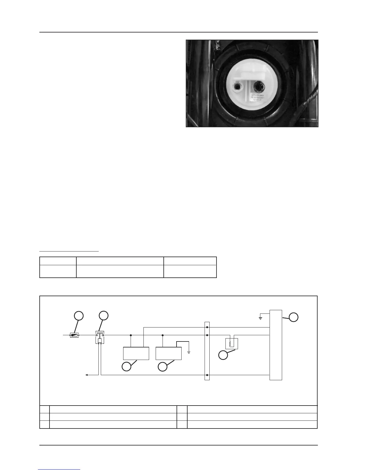
- Position the gasket on the tank.
- Install the pump support into its seat taking care to
align the connector with the longitudinal axis of the
vehicle.
NOTE: incorrect orientation may compromise the func-
tioning of the level indicator.
- Screw the fixing ring nut fully on.
Tightening torque:
Electropump locking ring nut 20 N·m
- Reconnect feed circuit tubes, checking correct inser-
tion via upwards traction and rotation.
- Reconnect the electrical connection.
- Reload the system with at least 4 - 5 timings (key
switch OFF-ON)
NOTE: do not activate the pump without fuel in the tank.
Failure to respect this regulation causes damage to the
pump.
- Check the seal of the quick-connections of the supply
system.
Injector circuit control
Terminals Conditions Standard
13-23 During timing of the pump Battery tension
with the engine stopped
2
20
23
19
1
86
85
30
87
13
1
2
+
3
4
5
6
CIRCUIT DIAGRAM
ELECTRONIC CONTROL UNIT
INJECTOR
HV COIL
PUMP
CONTROL UNIT ELECTRMAGNETIC SWITCH
10A FUSE
4
5
6
1
2
3
+ To the main
electromagnetic
switch
 Loading...