8 - 16
05_254
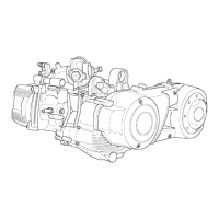
- Assemble the countershaft with the gear on the half
crankcase flywheel side
- Fit the specific tool in the position shown in the figure
Specific tool:
Countershaft lock wrench 020479Y
05_282
- Hold the countershaft and fit the washer with nut
- Tighten the nut to the prescribed torque, apply
LOCTITE 242
- Remove the specific tool.
Tightening torque:
Countershaft fixing nut: 25 - 29 N·m
Driving shaft crankcase
Driving shaft assembly
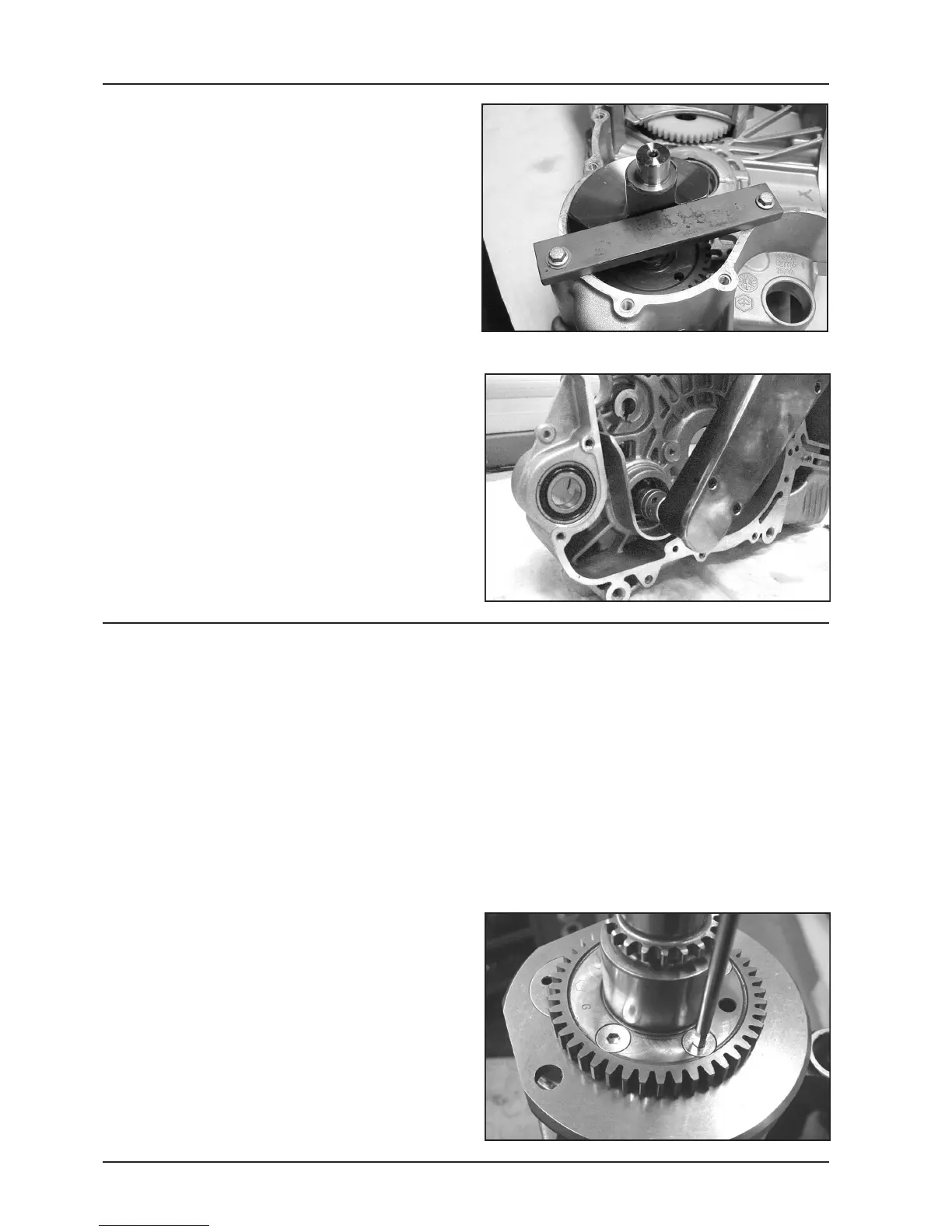
- Check that the countershaft control gear and the oil
pump show no signs of dents or deformation. Re-
place if necessary.
N.B.: If the countershaft control gear and the oil pump
are to be replaced, also replace the countershaft gear.
- Before assembling the gear on the driving shaft,
carefully clean the two coupling surfaces by removing
any residuals of LOCTITE from the holes by means of
a brush.
Blow compressed air and degrease the fixing holes
on both surfaces to improve the new LOCTITE set-
ting.
Apply LOCTITE 242 again.
- Repeat the same procedure for the 4 fixing screws.
- Fit the control gear on the driving shaft with the holes
countersink well visible.
- Tighten the 4 fixing screws to the prescribed torque.
N.B.: In order not to damage the screws control hexa-
gon, use a socket wrench with inner hexagon.
Tightening torque:
Driving shaft gear fixing screws: 10 - 12 N·m
05_283
 Loading...