8 - 14
Coupling
surface
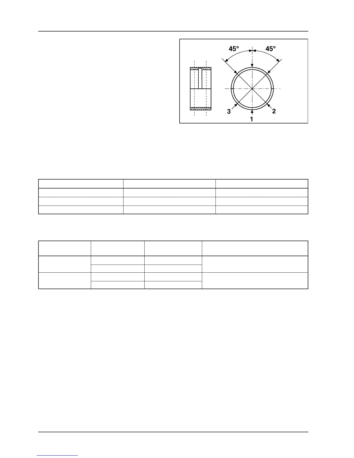
- Check the brasses diameter in the 3 directions shown
in the figure.
- Repeat the measuring on the other half of the brass.
See figure.
N.B.: Do not measure the mating of the 2 half bearings
as the ends are splined to allow deformation while
being fitted
- The brasses standard diameter after the driving
changes according to the coupling selected.
- The brasses housing in the crankcases are subdi-
vided in 2 classes, as for the driving shaft Class 1 and
Class 2.
- The brasses are subdvided in 3 classes depending
on the thickness, see table below:
05_277
N.B.: When assembling the spare parts, use the shaft with two shoulders class 1 with crankcase FC1 (or class 2 with
crankcase FC2).
A spare crankcase cannot be used with a mixed class driving shaft. The shaft for the spare parts is provided with
half shafts of the same class.
Driving shaft crankcase
TYPE IDENTIFICATION THICKNESS
A Red 1.982 - 1.987
B Blue 1.987 - 1.992
C Yellow 1.992 - 1.997
Half shafts coupling with half crankcase and brass
Half shaft Half shaft Brass Spare crankcase
Class Class class preparation
1 B FC1
2 C Drg. CM1033015001
1 A FC2
2 B Drg. CM1033015002
1
2
N.B.: To replace the half crankcases, remove the coun-
tershaft bearings as described above. Remove from the
half crankcase, transmission side, the antiflapping roller
and the driven pulley assembly, as described in Chapter
3-Automatic transmission, and the hub cover with rel-
evant gears and bearings, as described in Chapter 4-
Final Reduction.
 Loading...