7 - 11
7
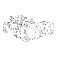
- Measure the cylinder inside diameter by means of a
reamer in the directions shown in the figure and at
three different heights.
Standard diameter: 92
+ 0.018
mm
- Make sure that the lining is not exfoliated.
- Check that the head coupling surface shows no signs
of wear or deformation.
Maximum allowed runout: 0,05 mm
- The pistons and cylinders are classified according to
their diameter. The coupling is made under the same
conditions (A-A, B-B, C-C, D-D).
Piston
- Carefully clean the gas ring slots.
- With suitable feelers, measure the allowance be-
tween the gas rings and piston slots as shown in the
figure.
- If values higher than those indicated in the table are
measured, replace the piston.
N.B.: Measure the play by inserting the feeler gauge
blade on the 2nd gas ring side.
05_186
05_187
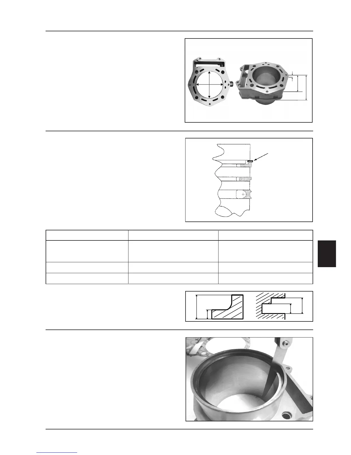
Gas rings
- Insert alternately the 3 gas rings in the cylinder, in the
area of its original diameter. Insert the rings orthogo-
nally to the cylinder axis using the piston to such
purpose.
- Measure the gas rings opening (see figure) by means
of a feeler gauge.
- If values higher than those prescribed are measured,
replace the rings.
05_188
Thermal unit and timing system
+ 0.010
Feeler gauge
Standard allowance Maximum allowance allowed after use
1st compression ring A=0.9
- 0.005
mm C=0.9
+ 0.03
mm
B=1.5
- 0.005
mm D=2
+ 0.05
mm
2nd compression ring 12
- 0.005
mm 1.25
+ 0.03
mm
Scraper ring 2.5
- 0.005
mm 2.5
+ 0.03
mm
 Loading...