9 - 99
9
Fuel injection
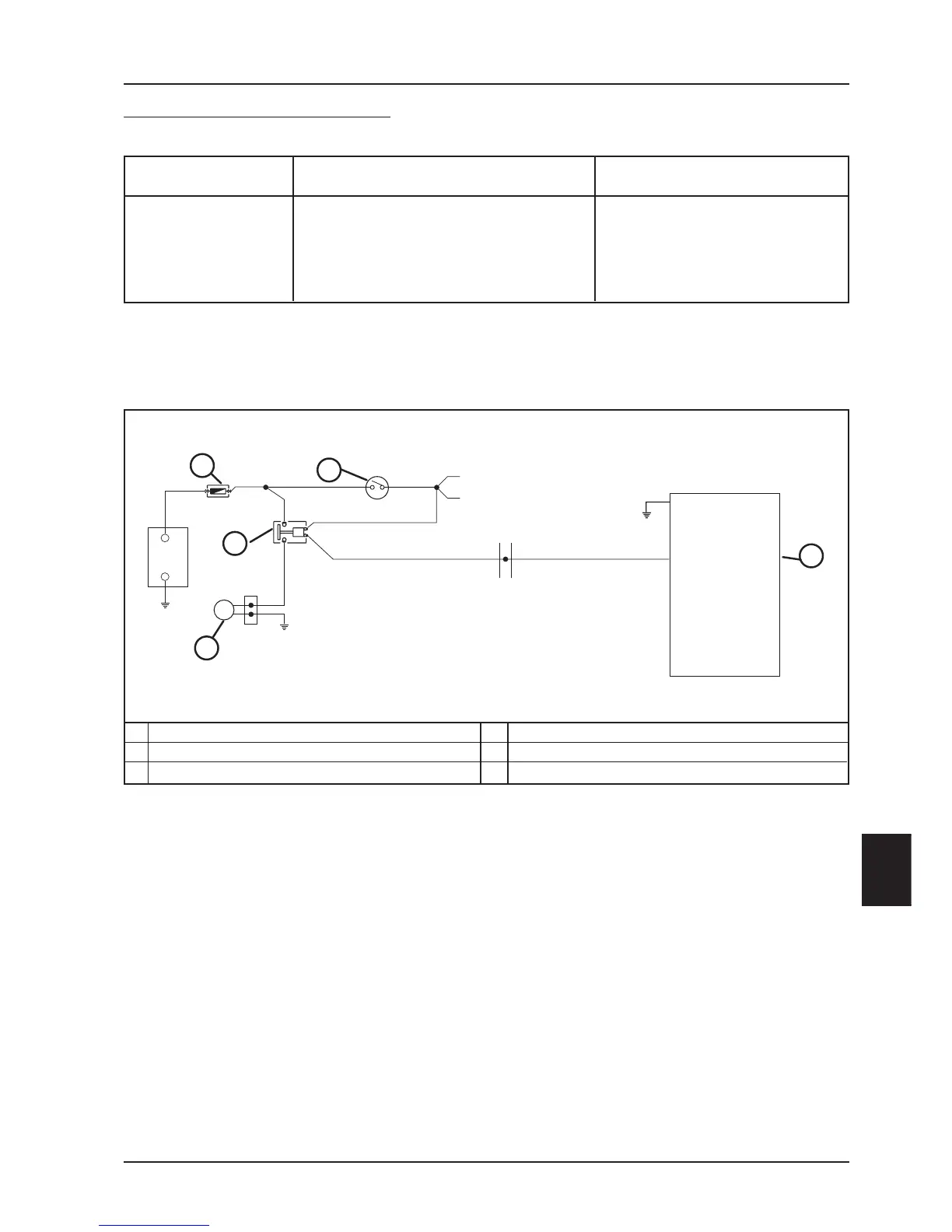
CIRCUIT DIAGRAM
The electrical ventilation system is fed by an electromagnetic switch connected under the panel and controlled by
the fuel injection control unit.
The fuel injection control unit manages control of the electrical fan on the basis of temperatures revealed by the
engine.
If a prolonged rotation of the electrical fan should occur, before proceeding with electrical system controls, check
accurately:
- level of the expansion tank
- drain from the tube leading to the engine
- drain on outlet from the cylinder head
- thermostat efficiency
- pump efficiency.
For these controls, see chapter 11-COOLING.
ELECTRICAL FAN CONTROL CIRCUIT
Terminals Conditions Standard
5-23 Set ignition to position "ON"
Switch on "RUN" Battery
Side stand raised tension
Electrical fan stopped
1
2
3
CONTROL UNIT
ELECTRICAL FAN
30A FUSE
KEY IGNITION
ELECTRICAL FAN ELECTROMAGNETIC SWITCH
4
5
23
1
5
86
85
30
87
M
3
4
5
+
-
2
 Loading...