11 - 7
11
Cooling
05_497
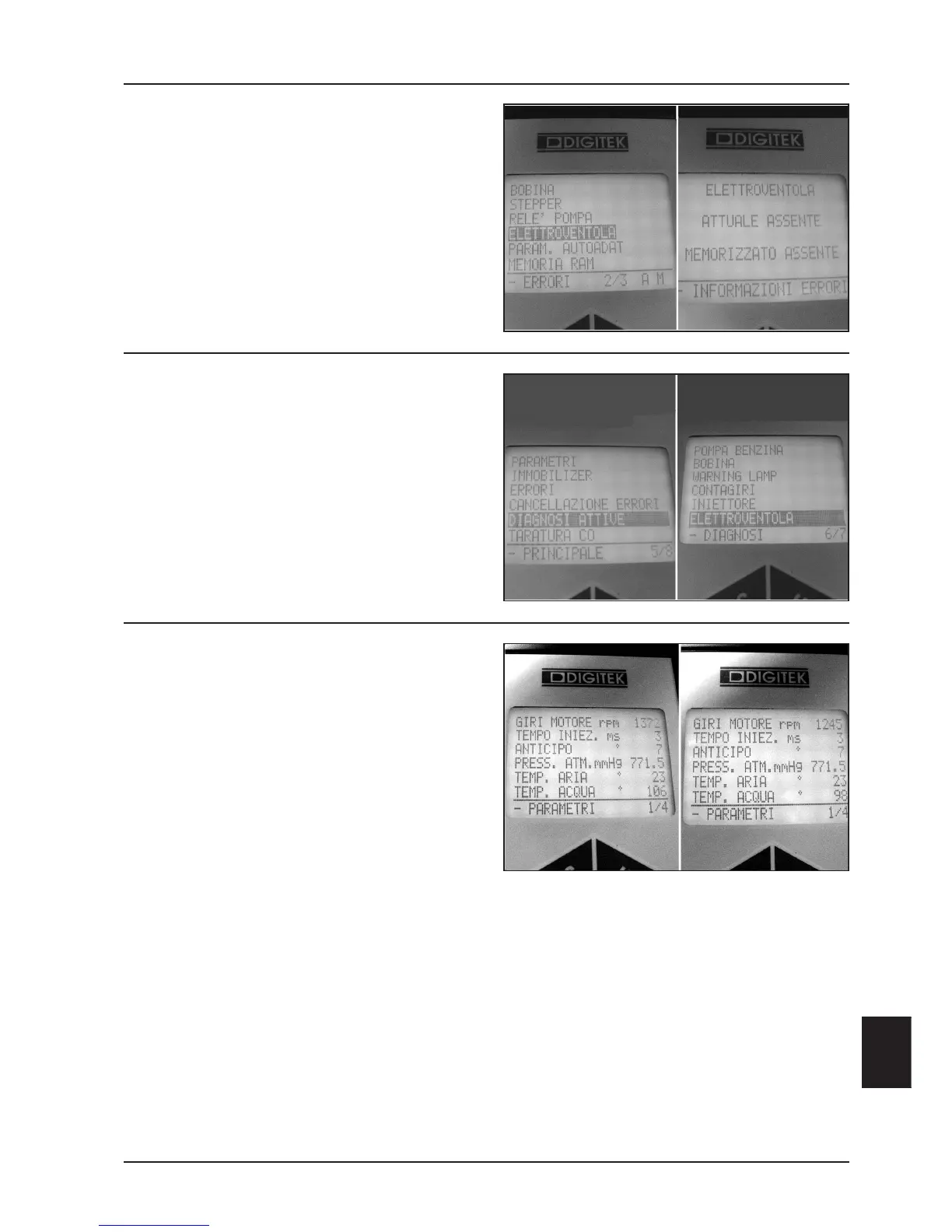
Electroventilation control
- Connect the fuel injection diagnosis tester and select
the “ERRORS” function from the menu.
- Check the presence of anomalies in the electrical fan
control circuit (See Chapter “FUEL INJECTION”).
Specific tool:
Fuel injection diagnosis tester 020460Y
05_498
- Select the “ACTIVE DIAGNOSIS” function from the
menu and command working simulation of the elec-
trical fan (see Chapter 9-FUEL INJECTION);
- With a certainly efficient electrical fan, check the
initial temperature after ventilation.
05_499
- Select the “PARAMETERS” function from the menu,
visualizing the coolant temperature.
Electrical fan activation: 106° C
Electrical fan disactivation: 98° C
- On revealing non-conformant values proceed with
replacement of the fuel injection control box (see
Chapter 9-FUEL INJECTION);
- If the temperature indication on the analogic instru-
ment is close to the red area, but the indication in
degrees on the diagnosis tester is less than the
electrical fan temperature, proceed with a check on
the head temperature sensor and related fuel injec-
tion circuit (see Chapter 9-FUEL INJECTION);
N.B.: The electroventilation temperature of 106° C is
manageable only with a system filled with a
50-50 mixture and pressurized to 0.9 bar.
Avoid engine functioning without pressurization so as
not to risk overheating the engine without having first
inserted the electrical fan.
If the electroventilation times increase, check the initial
opening temperature of the thermostat and the correct-
ness of coolant density.
Optimum density is obtained with a 50-50 mixture of
water and circuit coolant.
 Loading...