Fuel injection
9 - 40
Pump feed circuit
The control unit intervenes by activating the pump under the following conditions:
- setting to "ON" with emergency switch set to "RUN" and side stand raised.
Pump feed for 2 seconds.
- when the phase revolutions signal is present.
Continuous feed
The initial timing is useful to drain the system, especially after leaving the vehicle parked with the engine
warm. In these conditions, fuel altered by overheating will be mixed with that in the tank.
During use, the pump function will be subordinated by the engine revolutions.
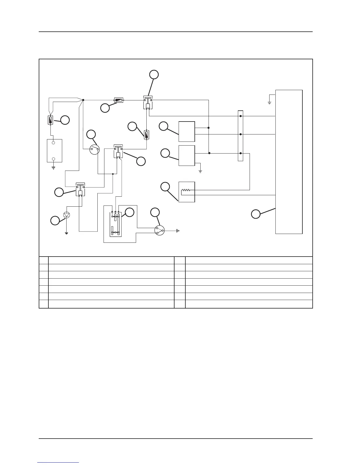
CIRCUIT DIAGRAM
1 30A FUSE 8 FUEL PUMP
2 10A FUSE 9 INJECTOR
3 COMMUTATOR 10 FUEL INJECTION CONTROL UNIT
4 ENGINE STOP ELECTROMAGNETIC SWITCH 11 MAIN ELECTROMAGNETIC SWITCH
5 5A FUSE 12 2A DIODE
6 ELECTROMAGNETIC SWITCH 13 ENGINE STOP SWITCH
7 H.V. COIL 14 STAND SWITCH
2
3
6
7
8
10
23
86
85
30
87
86
85
30
87
19
20
13
1
2
4
86
85
30
87
5
1
+
-
11
12
13 14
9
 Loading...